
Output current boost circuit PGA202 OPA633

The circuit design incorporates the PGA202, which serves as the primary operational amplifier, providing initial signal amplification. The OPA633 is connected in a configuration that allows it to boost the output current of the PGA202. This arrangement is particularly beneficial in applications where increased current drive capability is essential, such as in driving low-impedance loads or in systems requiring higher power outputs.
The PGA202 features a programmable gain architecture, allowing for flexibility in gain settings, which can be adjusted according to the specific requirements of the application. The OPA633, known for its high-speed performance and low distortion, complements the PGA202 by providing additional output current without compromising the overall signal integrity.
In this configuration, feedback mechanisms are critical to maintaining stability and ensuring that the output remains linear across the desired frequency range. Proper selection of feedback resistors and compensation capacitors is necessary to optimize performance and prevent oscillations. Additionally, power supply decoupling capacitors should be included close to the power pins of both amplifiers to minimize noise and ensure stable operation.
This current boosting circuit can be utilized in various applications, including audio amplification, sensor signal conditioning, and high-speed data acquisition systems, where robust output current capabilities are required. The integration of the PGA202 and OPA633 creates a versatile and powerful solution for enhancing output current in electronic circuits. As shown in FIG grounds PGA202 OPA633 op amp output current boosting circuit configuration. This circuit PGA202 output of an operational amplifier plus the ability OPA633, OPA6 33 output current use, to enhance the output current of the entire circuit.
Related Circuits
The LM35 from National Semiconductor is a precision centigrade temperature sensor that provides an analog output voltage. It operates within a temperature range of -55°C to +150°C and has an accuracy of ±0.5°C. The output voltage corresponds to 10mV...
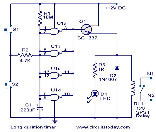
This timer circuit is designed to turn off a specific device after approximately 35 minutes. It can be utilized to switch off appliances such as radios, TVs, fans, and pumps after a predetermined duration of 35 minutes, contributing to...
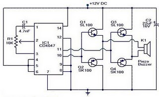
The circuit operates on the principle that insects, such as mosquitoes, can be repelled using sound frequencies in the ultrasonic range (above 20 kHz). It utilizes a Phase-Locked Loop (PLL) integrated circuit, specifically the CMOS 4047, configured as an...
This circuit is similar to the previous one but employs positive feedback to enhance the amplitude delivered to the speaker. It was adapted from a small five-transistor radio that utilizes a 25-ohm speaker. In the prior circuit, the load...
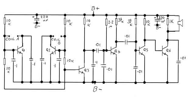
By adjusting the oscillators so their frequencies are very nearly the same, the difference between them is made audible as a beat note. This beat note changes slightly when the search loop is moved over or near to a...
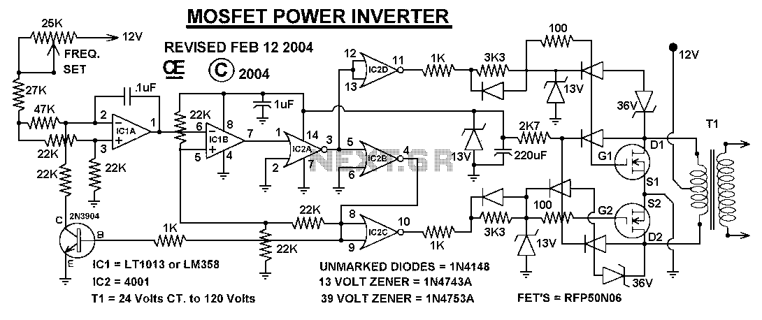
This power inverter circuit provides a stable square wave output voltage. The frequency of operation is set by a potentiometer and is typically adjusted to 60 Hz. Various off-the-shelf transformers can be utilized, or custom-wound transformers can be created...