
High Frequency Generator Circuit

The circuit utilizes the MAX038 integrated circuit, which is specifically designed for generating various waveform outputs including sine, triangle, and square waves. The fundamental operation of the circuit relies on the internal voltage-controlled oscillator (VCO) of the MAX038, which can be adjusted by changing the input current. The adjustment of frequency through current modulation allows for precise control over the output waveform characteristics.
To implement the frequency control via a microcontroller, the DAC should be connected to the RIN pin after removing the 20k resistor. The microcontroller can provide a digital signal that the DAC converts into an analog voltage, thereby controlling the frequency of the output waveform. This method allows for dynamic frequency adjustments in real-time, making it suitable for applications requiring variable waveform generation.
The PLL functionality enhances the circuit's versatility by allowing synchronization with an external reference clock. By connecting a quartz crystal oscillator to the reference input, the circuit can maintain stable frequency outputs, which is particularly advantageous for applications needing high accuracy and stability.
The output frequency range of 0.1 Hz to 20 MHz indicates the circuit's capability to serve a wide variety of applications, from low-frequency signal generation for audio applications to high-frequency signals for RF communication. The ability to produce multiple waveform types further increases the utility of the MAX038 in various electronic projects, including signal processing, testing, and simulation tasks. This flexibility makes the circuit an essential component in waveform generation systems.This circuit generate sine wave oscillation, but actually we can modify the circuit to generate triangle or square wave function. The frequency can be controlled using current. If we disconnect the 20k RIN from REF (pin 1) and connect it to a DAC, then we can control the frequency using microcontroller or digital interface.
We can even control the chip using a quartz crystal (PLL) by controlling the current using a phase comparator output that compares the sync output (pin 14 of MAX038) and a reference clock from quartz crystal oscillator. This waveform generator integrated circuit chip is very interesting since it can generate 0. 1Hz to 20MHz, very wide operating frequency, as expected for every waveform generator instruments. 🔗 External reference
Related Circuits
In an audio amplifier, the quality of sound depends on several factors, including the quality of active and passive components, circuit configuration, and layout. The selection of components is influenced by the constructor's budget. Discrete active components like transistors...
The Lorenz system is one of the few standard oscillators commonly used to explore chaos. An accessible description of its mathematical features and chaotic dynamics is presented by Thompson and Stewart. This important system was originally developed as a...
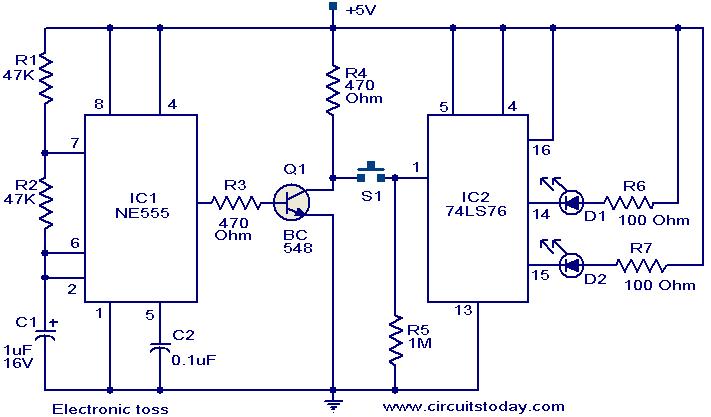
The circuit described can be utilized for tossing a coin, serving as a random generator for head or tail outcomes. This circuit is applicable in various games where a coin toss is required to initiate play. It employs two...
The output voltage is = 0.707 x Vin, at the center position. The output voltage is = Vin, at either extreme position. This circuit appears to describe a variable output voltage system, likely utilizing a potentiometer or a similar adjustable...
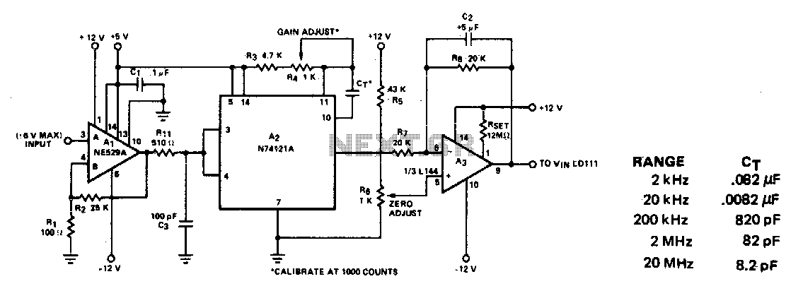
This circuit converts frequency to voltage by taking the average DC value of the pulses from the 74121 monostable multivibrator. The one-shot is triggered by the positive-going AC signal at the input of the 529 comparator. The amplifier acts...
The two circuits below illustrate the generation of low-frequency sine waves by shifting the phase of the signal through an RC network, ensuring that oscillation occurs when the total phase shift reaches 360 degrees. The transistor circuit on the...