
High frequency signal generator

The circuit described employs a tapped-coil Colpitts oscillator, which is a type of oscillator known for its stability and ability to produce a range of frequencies. The oscillator's tuning ranges, spanning from 1.7 to 31 MHz, are facilitated by the tapped coil configuration, which allows for different resonant frequencies to be accessed through adjustments in the coil taps. The inclusion of a Zener diode (D2) at Q1 is critical, as it regulates the voltage supplied to the oscillator, thereby enhancing its performance and reliability.
Capacitor C5 plays a vital role in coupling, ensuring that the oscillator operates efficiently without excessive loading on the tuned circuit. This careful coupling is essential for maintaining the oscillator's frequency stability and performance. Q2, acting as a source-follower buffer, provides impedance matching between the oscillator and the load, preventing any adverse effects on the oscillator's operation due to variations in load impedance.
RFC1, a radio frequency choke, is employed to tune the source of Q2, allowing for broader frequency adjustments and improving the overall response of the oscillator. This tuning is crucial for optimizing the performance of the oscillator across its specified frequency ranges.
The energy output from Q2 is fed into a feedback broadband class amplifier, which amplifies the signal while maintaining a wide bandwidth, ensuring that the oscillator's output remains consistent across its tuning ranges. The 2 dB attenuator at the output of T1 serves to match the output impedance to 50 ohms, which is a standard impedance for RF applications, thereby minimizing reflections and maximizing power transfer to subsequent stages.
Furthermore, the RF decoupling network formed by capacitors C16, C17, and RFC2 is essential for suppressing unwanted RF emissions. This network prevents the oscillator's energy from radiating into the environment, which could lead to interference with other electronic devices. By effectively isolating the oscillator from the 12 V supply, the circuit ensures cleaner operation and compliance with regulatory standards regarding electromagnetic interference. Overall, this design exemplifies careful consideration of component selection and circuit topology to achieve a reliable and effective oscillator circuit.A tapped-coil Colpitis oscillator is used at Ql to provide four tuning ranges from 1.7 to 3.131Hz, 3.0 to 5.6 MHz, 5.0 to 12 MHz and 11.5 to 31 MHz. A Zener diode (D2) is used at Ql to lower the operating voltage of the oscillator. A small value capacitor is used at C5 to ensure light coupling to the tuned circuit. Q2 is a source-follower buffer stage. It helps to isolate the oscillator from the generator-output load. The source of Q2 is broadly tuned by means of RFC1. Energy from Q2 is routed to a fed-back, broadband class- amplifier. A 2 dB attenuator is used at the output of Tl to provide a 50 ohm termination for Q3 and to set the generator-output impedance at 50 ohms. C16, C17 and RFC2 form a brute-force RF decoupling network to keep the generator energy from radiating outside the box on the 12 V supply.
Related Circuits

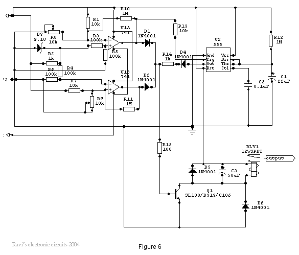
Power line fluctuations and cut-offs can damage electrical appliances connected to the line, particularly domestic appliances such as refrigerators and air conditioners. Operating a refrigerator on low voltage can lead to excessive current flowing through the motor, resulting in...
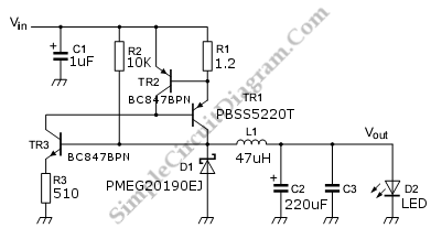
This is a discrete high-current switch-mode LED driver circuit. The fundamental principle of this circuit is based on the buck-converter topology. The efficiency of this circuit is 80%. The discrete high-current switch-mode LED driver circuit utilizes a buck converter configuration...
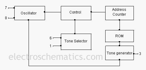
The UM3561 is a versatile ROM integrated circuit capable of generating multiple siren tones, including those that simulate police sirens, ambulance sirens, fire brigade sirens, and machine gun sounds. This low-power, 8-pin IC operates down to 2.4 volts and...
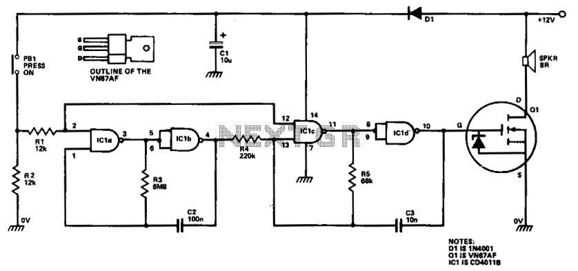
ICla and IClb are configured as a slow astable multivibrator, while IClc and ICld are arranged as a fast astable multivibrator. The output from the slow astable modulates the frequency of the fast astable, and the output from the...
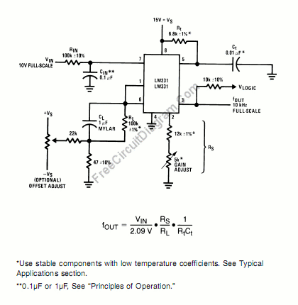
A voltage-to-frequency converter can be constructed using the LM231/331 chip, making it a cost-effective solution for applications such as analog-to-digital conversion and frequency-to-voltage conversion over extended periods. The LM231/331 series of voltage comparators can be effectively utilized to design a...
The under/over voltage protection circuit with time delay presented here is a low-cost and reliable circuit for protecting equipment from damage. This under/over voltage protection circuit is designed to safeguard electronic equipment from voltage fluctuations that can lead to potential...