
High And Low Voltage Cut Off With Time Delays

This under/over voltage protection circuit is designed to safeguard electronic equipment from voltage fluctuations that can lead to potential damage. The circuit operates by monitoring the input voltage levels and activating a protective mechanism when the voltage exceeds or falls below predetermined thresholds.
Key components of the circuit typically include a voltage sensing device, such as a Zener diode or a voltage comparator, which continuously measures the input voltage. When the sensed voltage deviates from the set limits, the circuit initiates a delay mechanism, often implemented using a timer IC, such as the 555 timer, to prevent nuisance tripping due to transient voltage spikes or dips.
The design incorporates a relay or a solid-state switch that disconnects the load from the power source when the voltage is outside the acceptable range. The time delay feature is crucial as it allows temporary voltage fluctuations to stabilize before the protective action is taken, thus ensuring that the equipment remains operational during brief disturbances.
Additionally, the circuit can be enhanced with indicators, such as LEDs, to provide visual feedback on the operational status and fault conditions. This feature aids in troubleshooting and maintenance by clearly indicating whether the circuit is active or has tripped due to voltage irregularities.
Overall, this under/over voltage protection circuit is an essential component in various applications, including industrial machinery, consumer electronics, and telecommunications equipment, ensuring longevity and reliability by preventing damage from voltage anomalies.The under/over voltage protection circuit with time delay presented here is a low cost and reliable circuit for protecting such equipments from damages.. 🔗 External reference
Related Circuits

Pulse size and width are independent of pulse energy or other properties of the event. Geiger-Mueller tubes have reduced sensitivity to non-gamma-ray radiation and exhibit poor dose-rate calibration accuracy. They are commonly used due to their favorable balance of...
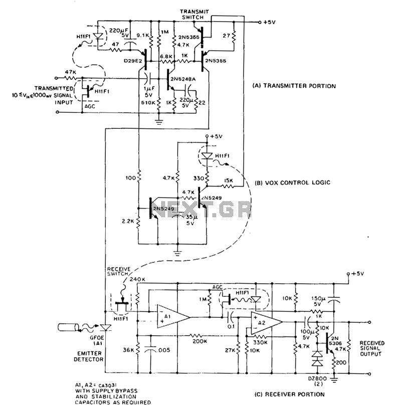
In a half-duplex system, information can flow in both directions, but only one direction at any given time. The conventional method of building a half-duplex link requires a separate emitter and detector, connected with directional couplers, at each end...
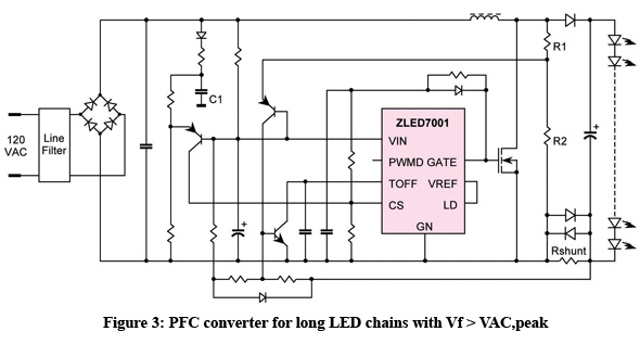
The incandescent light bulb has been the leading choice for lighting applications since its introduction in the late 19th century; however, its efficiency has consistently remained below five percent. Growing global ecological awareness and the demand for more cost-effective...

The circuit operates as a unijunction transistor relaxation oscillator. The base of the lower PNP transistor is biased at approximately half of the supply voltage. As the 100pF capacitor charges through the 1GΩ resistor, the base of the upper...
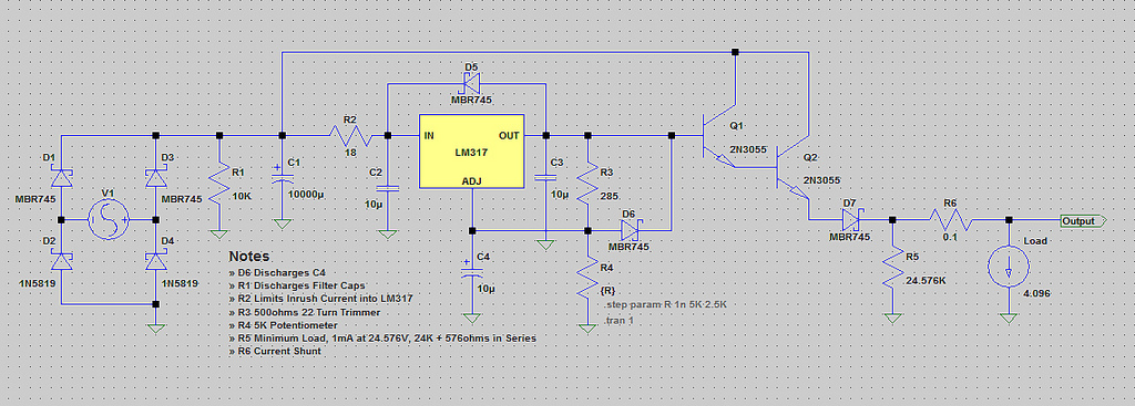
The voltage range will be from 0V to 24V, and the current is not expected to exceed 4A. A microcontroller and an LCD could potentially be added to measure voltage and current. The schematic appears to be generally acceptable....
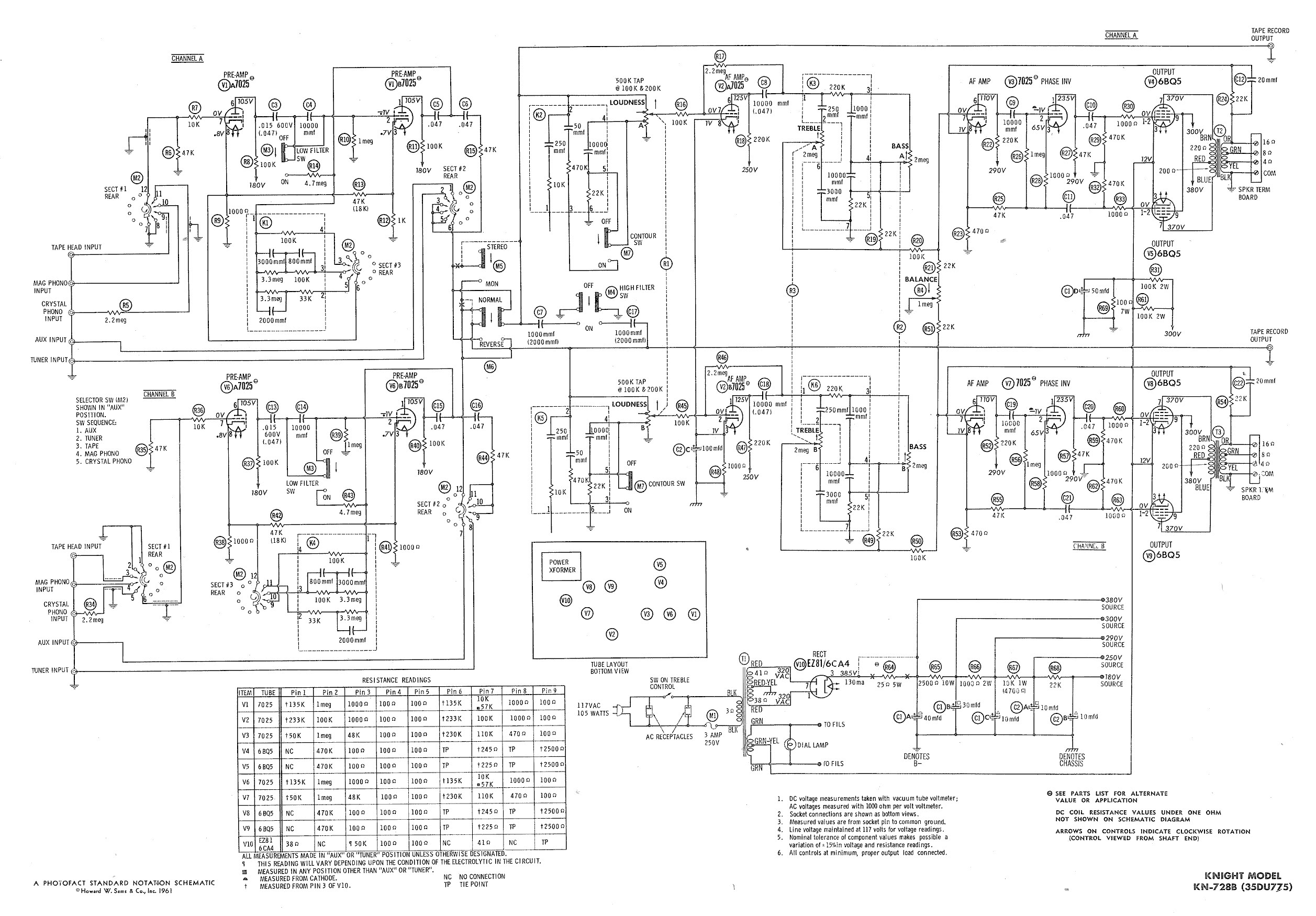
Ty - Concerning the updated schematic of the AF/PI stage, it appears that resistor R45 is not present. Additionally, the disk capacitor bypassing R44 is marked as 68nF750 with a tolerance of 10%, which is presumed to be the...