
High-Quality Stax Headphone Adapter

The circuit design for the Stax SRD-7MkII headphone adapter emphasizes high fidelity and safety. The voltage multiplier circuit consists of six stages, effectively stepping up the input AC voltage to a maximum output of 600VDC while ensuring minimal power consumption. This design mitigates the risk of high output voltages during short-circuit conditions, thanks to the high impedance of the voltage multiplier. Furthermore, the output is connected to a 5 MΩ resistor, which further reduces voltage in case of a fault, enhancing user safety.
To accommodate various electrostatic headphone models, the circuit includes provisions for adjusting the output voltage. This versatility allows users to tailor the adapter for different headphone specifications, making it a valuable tool for audiophiles who own multiple headphone types. The connection to the mains without an isolation transformer, while not ideal, is a practical necessity for fitting the design into the existing Stax SRD chassis. The recommendation for an isolation transformer serves to minimize potential hum and noise, ensuring a clean audio signal.
The incorporation of LED indicators for power status is a modern enhancement that improves user experience. While neon bulbs function adequately at high voltages, LEDs offer a more visually appealing and energy-efficient alternative. The chassis preparation is a critical first step, requiring precision in hole placement to ensure all components fit securely and function correctly. By following the provided guidelines and utilizing proper measuring techniques, users can achieve a professional assembly, ensuring optimal performance of the Stax SRD-7MkII headphone adapter.This project allows one to build a very high quality version of the Stax SRD-7MkII headphone adapter to allow one to use an existing favorite amplifier to power your stax headphones. (Let Birgir know what amplifier you have to find out if the adapter is possible in your setup. ) If you can find a used SRD-7MkII, which are pretty rare, it likely wou ld be less expensive (~$300 ) than the project adapter. But because this project uses high quality parts (mainly the James Transformers, Teflon insulation silver coated wiring, and silver solder), you might achieve superior sound quality. I have had a SRD-7MkII and I believe subjectively that the project adapter achieves superior channel separation, instrument isolation, detail and bass quality.
Included below is a complete parts list. Total parts cost is about $400 - $500. I don`t have the receipts for a few parts but I estimated the cost on those. I only added a normal bias stax connector since I use the wonderful Stax Lambda Normal headphones. But the circuit board allows connection for both normal and high (pro) bias, and one could easily cut another hole in the chassis for another Stax headphone connector so that you can have both possibilities available like the SRD-7MkII does. It took me about 4 months to build working as time permitted. I think that this could be finished in a week or less if one has the dedicated time. I`ve been using this for nine months with perfect operation. Thanks so much to Birgir for his help throughout the project. Please feel free to comment and suggest improvements. 14 ga Silver-coated wire (Teflon-insulation I think) for Speaker Circuit and what I have been using as speaker wire for many years (bought from Scott Welbourne many years ago) The circuit is based around a voltage multiplier (six stages) with a limited input voltage.
The supply takes the AC mains voltage from the wall, limits to 100V and then steps it up six times and rectifies it in the process. Now the circuit uses virtually no power at all but in case of a short the high impedance nature of the voltage multiplier will make the output voltage fall well short of the 600VDC so this is very safe in practice.
The output is also fed through a 5Mohm resistor so in case of a short the voltage will be reduced even further. The supply also has spots for a voltage divider on the output of the multiplier which allows for output for virtually any electrostatic headphone.
The voltage can be cut down to 230V for the normal bias Stax models (done in the case of this article), 540V for the Sennheiser HE60, 500V for the Sennheiser Orpheus or 180V for the Beyer Dynamic ET-1000. The supply being connected directly to the mains and not through an isolation transformer isn`t ideal but it had to be done so that these boards would fit in the old Stax SRD line of adapter boxes.
This setup can cause hum issues so I would recommend a small isolation transformer (4VA is plenty) between the IEC input and the boards. Next version of the boards will have built in transformers but that will have to wait until I (Birgir) run out of the current version of the boards.
On the latest version of the supply I also added a small circuit that allows the use of LED`s for power indication. Stax used neon bulbs in their boxes which work just fine off the high AC voltages but LED`s need much lower voltages.
Neon NE-2 bulbs can still be used but the LED`s look much better. The first step in the project is to measure the positions for and make all of the holes in the aluminum chassis for the parts to be mounted. Some of the packaging for the parts provides measurements for the proper hole size to drill. Create a template out of paper and lay out the holes on the chassis for each side depending on how you want everything placed.
For those parts that don`t have defined drill sizes, one can measure the part itself or place it against the paper and trace it out. We did o 🔗 External reference
Related Circuits
A small headphone amplifier is a valuable device capable of driving multiple pairs of headphones. The headphone amplifier's task is simplified due to the relatively low output power requirements and the manageable load characteristics. Headphones generally have an impedance...
Using this low cost project, one can reproduce audio from a TV without disturbing anyone. It does not use any wire between the TV and headphones. Instead of a pair of wires, it uses invisible infrared light to transmit...
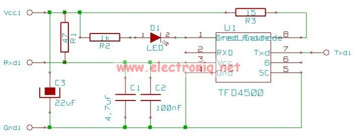
This electronic infrared adapter serial transceiver circuit is based on a TFDS4500 IC and can be used to transmit data from portable devices to a PC using infrared (IR) and a serial port. The TFDS4500 infrared adapter is a...
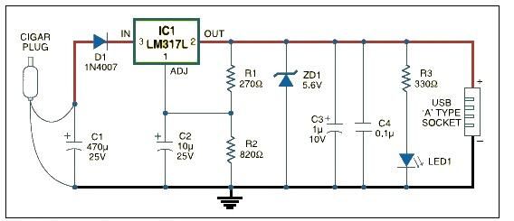
This USB car charger adapter project functions as a DC-DC power converter that effectively converts the 12V car battery voltage into a stable 5V output. It is designed to supply power from a car's cigar lighter socket to any...
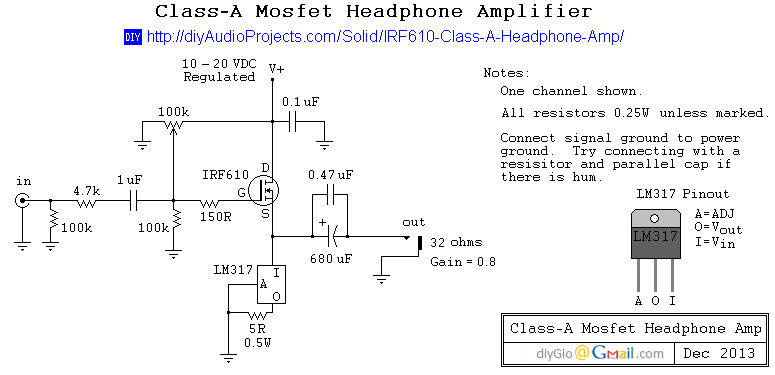
This is a simple and low-cost desktop headphone amplifier designed for office use. The amplifier concept is straightforward and adheres to a typical single-ended Class A circuit. The desktop headphone amplifier utilizes a single-ended Class A design, which is known...
The NE5532 preamplifier is widely recognized for its excellent performance. It is now being utilized as a small power amplifier. While the general operational amplifier (op-amp) circuit remains similar, there are notable changes in some resistors and capacitors, leading...