
High Side Current Sensing for Low Side Switching

The AD8205 is an instrumentation amplifier specifically designed for high-side current sensing applications. Its architecture allows for precise measurement of the voltage across the shunt resistor, which is critical for determining the current flowing through the inductive load. The high-side configuration is advantageous as it maintains the shunt in the measurement loop, even when the low-side switch is open. This feature ensures that the circuit can monitor and capture the re-circulation current that occurs in inductive loads, such as solenoids, when the switch transitions from on to off states.
In this circuit, the resistive shunt is selected based on the expected current range and the desired voltage drop for accurate sensing. The AD8205 amplifies the small voltage developed across the shunt, which is proportional to the current. The output of the AD8205 can be connected to an analog-to-digital converter (ADC) for further processing or monitoring.
The design also incorporates protection features to handle potential issues such as short circuits or voltage spikes. By placing the shunt on the high side, any shorts to ground can be detected, facilitating better diagnostics and maintenance of the system. The schematic diagram provides a visual representation of the connections between the AD8205, the shunt resistor, the inductive load, and the low-side switch, illustrating the flow of current and the points at which voltage measurements are taken.
When the low-side switch is closed, the common-mode voltage shifts towards the negative rail, which is essential for proper operation of the AD8205 within its specified common-mode range. When the switch is opened, the common-mode voltage may rise above the battery voltage due to the inductive kickback from the load, necessitating careful design considerations to ensure that the amplifier remains within operational limits.
This configuration is widely used in applications requiring accurate current sensing in automotive, industrial, and consumer electronics, where reliable performance and diagnostic capabilities are critical.An AD8205 can be used to make a high-side current sense with a low side switch. Besides AD8205, an inductive load (solenoid) and a resistive shunt are added in this circuit. The resistive shunt is placed on high-side and the switch is placed on low-side, so that all current measurements, including the the re-circulation current, can be done becaus e when the switch is off, the shunt still in loop. Besides that, placing the shunt on high side, shorts to ground can be detected, so diagnostics can be optimized. Here is the schematic diagram of the circuit: When we connect the switch, the common-mode voltage will move down to near the negative rail.
If we disconnect the switch, the common-mode voltage drop above the battery because of the voltage reversal that across inductive load. [Circuit`s schematic diagram source: Analog Application Note] We aim to transmit more information by carrying articles.
Please send us an E-mail to wanghuali@hqew. net within 15 days if we are involved in the problems of article content, copyright or other problems. We will delete it soon. 🔗 External reference
Related Circuits

This circuit is a programmable current source that utilizes the LT1102 operational amplifier from Linear Technology Corp. in conjunction with the LT1006 operational amplifier. The first amplifier (A1), biased by a voltage source, drives current through a resistor (R)...
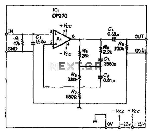
A common telecoil follows the MM formula (magnetic-acting) and has an impedance of approximately 600 ohms to effectively receive signals. It is necessary to reduce the impedance in the high-frequency segment, which is achieved by placing a 150pF capacitor...
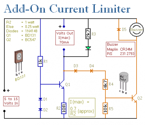
This circuit enables the user to establish a limit on the maximum output current from a power supply unit (PSU). It is particularly beneficial when powering up a project for the first time or conducting a soak test. By...
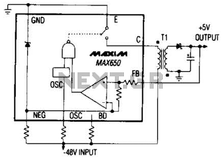
The Max650 switching regulator generates a regulated 5 V output from large negative voltages, such as the -48 V commonly found on telephone lines. This power supply requires several external components, including a transformer, and is capable of delivering...
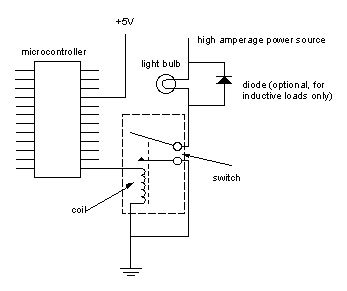
Digital output from a microcontroller is typically a low-amperage signal. For example, when a pin is set HIGH on the microcontroller (in Wiring/Arduino, it is digitalWrite(somePin, HIGH);), the voltage from that pin is usually +3.3V or +5V, with the...
The circuit begins with a step-down mains transformer featuring a secondary winding rated at 24 V/3 A, which connects across the input points at pins 1 and 2. The quality of the output supply is directly related to the...