
Voltage-Programmable Current Source

This programmable current source circuit is designed for applications requiring precise current delivery. The LT1102 operational amplifier serves as the main driver, providing the necessary gain and output characteristics to control the current through the load effectively. The inclusion of the LT1006 operational amplifier enhances the circuit's performance by enabling accurate current sensing and feedback control.
A key feature of this circuit is its ability to maintain stable operation across a range of load conditions. The feedback loop created by A2 allows for real-time adjustments to the output current based on the sensed value, ensuring that the output remains consistent despite variations in load resistance.
The choice of a 10-ohm resistor in the feedback path is critical, as it directly influences the output current magnitude. The 0.05 µF capacitor, in combination with the resistor, establishes the frequency response, allowing the circuit to respond effectively to dynamic changes in the load. This configuration is particularly useful in applications such as sensor excitation, LED driving, and precision measurement systems where current stability is paramount.
Overall, the combination of the LT1102 and LT1006 operational amplifiers, along with the carefully selected passive components, results in a robust and versatile programmable current source suitable for various electronic applications. This, circuit is a programmable current source in which op amp LT1102 (Linear Technology Corp.) is used in conjunction with LT1006 op amp. Al, biased by V^, drives current through R (10 ) and the load. A2 senses this current and controls Al. The 10-1 resistor and 0.05-/iF capacitor sets the frequency response of the circuit.
Related Circuits
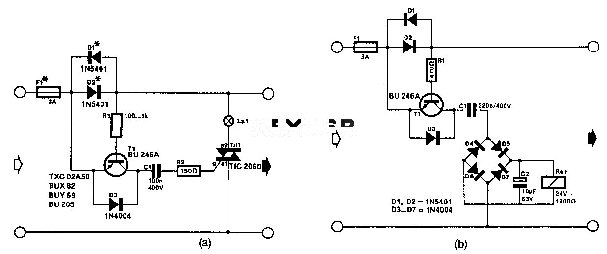
The circuit in Fig. 56-lla activates a signal lamp when it detects a line current consumption exceeding 5 mA and can handle currents of several amperes using suitable diodes in the D1 and D2 positions. Transistor T1 is activated...
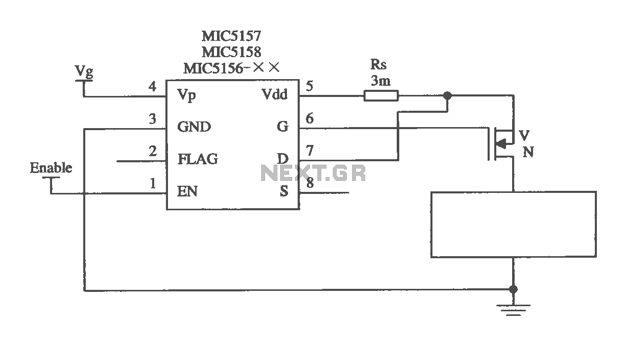
The MIC5156 is a device that incorporates a current limiting function, allowing it to handle high output currents. It can operate with or without a switching regulator circuit. The S terminal is left vacant, and a 16V Zener diode...
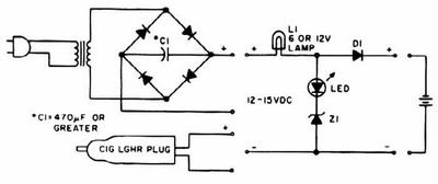
NiCd charger with current and voltage limiting power supply. This is a car NiCd battery charger circuit that can charge any Ni-Cd battery between 4.8 and 4.4 volts from a classic 12 volts car battery. The charging current can...
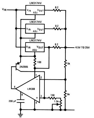
The LM317HV adjustable regulator is capable of supplying over 1.5A across an output voltage range of 1.2V to 57V. The design of this high current power supply is straightforward, as the LM317HV requires only a few external resistors to...
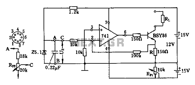
The Darlington transistor circuit BSY86 produces a large output current, with a maximum limit of 150 ohms. The output current is adjustable via resistor R and the RP1 potentiometer, maintaining constancy regardless of the load resistance Rl. The potentiometer...
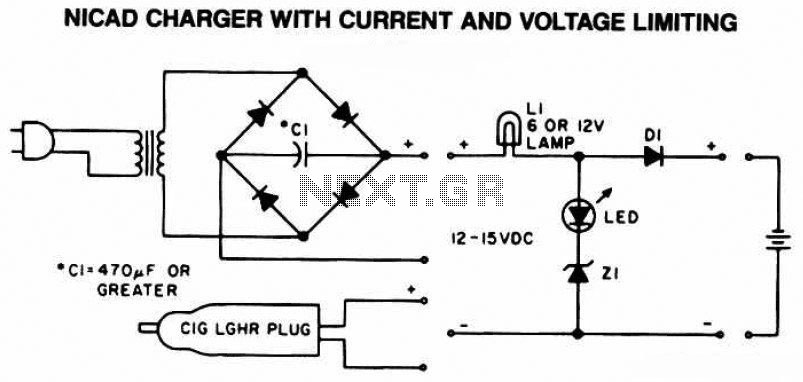
The following diagram is the schematic of a Ni-CAD battery charger circuit, which includes current and voltage limiting features to extend the battery's lifespan. The lamp L1 will illuminate brightly, and the LED will be off when the battery...