
High Speed Logic Astable Multivibrator (MC74HC04)
")
The MC74HC04 is a hex inverter, which means it contains six independent inverter gates. Each gate takes a single input signal and produces the inverse output. This IC is particularly suitable for low-cost applications and operates at a wide voltage range, making it versatile for various electronic designs. The choice of the 'HC' series is advantageous due to its high-speed performance and low power consumption compared to traditional TTL logic.
In the described circuit, the MC74HC04 is configured to create a simple oscillator. The resistors R1 and R2, along with the capacitor C, form a timing network that dictates the frequency of oscillation. The values of R1 (390kΩ) and R2 (680kΩ) are chosen to provide a suitable charge and discharge path for the capacitor C (10µF), allowing it to oscillate between high and low states.
LED1 serves as a visual indicator of the output state. When the output transitions from high to low, the LED will illuminate, providing a clear indication of the circuit's operation. The use of a 9V battery as the power source ensures that the circuit operates reliably across its components, while the 9V battery clip facilitates easy connections.
It is crucial to note that for the 'HC' type of the MC74HC04, any unused inputs must be connected to a defined logic level, either GND or VCC, to prevent floating inputs that could lead to unpredictable behavior. In contrast, the 'LS' type allows unused inputs to be left open, but this design choice may affect the performance and stability of the circuit.
The specified components, including resistors and the LED, should adhere to the stated tolerances and power ratings. All resistors are 1/4W with a tolerance of 5%, ensuring they can handle the required power without overheating. The choice of tantalum or electrolytic for the capacitor is important to maintain the stability of the oscillation frequency, as these types offer low equivalent series resistance (ESR) and good frequency response.
Overall, this circuit represents a straightforward implementation of a hex inverter in an oscillator configuration, demonstrating the fundamental principles of digital logic and timing circuits.The MC74HC04 IC is a low cost CMOS Hex Inverter. I used this type mainly because, it is what I have, although you can use LS type but, with a little modification or exemptions.. For 'HC' type: Always connect unused inputs to an appropriate voltage level (e.g. GND, or VCC), unused outputs can be left open. For 'LS' type: You can leave unused inputs open as well as unused outputs. The figure below is the schematic layout for the circuit. The circuit makes use of passive components R1, R2 and capacitor C to make the oscillation. LED1 serves as the output indicator for the High to Low transition of the circuit. PARTS ----------------------------- IC1 = MC74HC04 (1) R1 = 390kΩ (1) R2 = 680kΩ (1) R3 = 330Ω (1) C = 10uF/16V tantalum/electrolytic (1) LED1 = 5mm LED Diode any color (1 each) 9V Battery, 9V Battery Clip (1 each) * All resistors are 1/4W 5% tol. carbon composition type unless specified. 🔗 External reference
Related Circuits
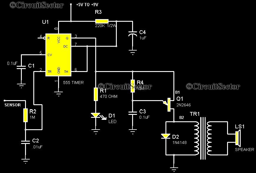
This is a highly sensitive touch plate circuit utilizing the NE555 timer IC, which activates a buzzer when a person touches the metal plate or hovers their hand above it. Compared to previously published touch control switch circuits, this...
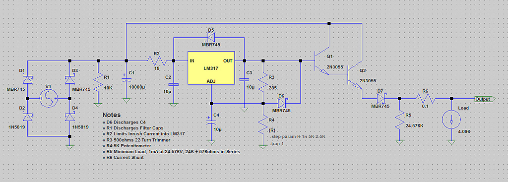
The voltage range will be from 0V to 24V, and the current is not expected to exceed 4A. A microcontroller and an LCD could potentially be added to measure voltage and current. The schematic appears to be generally acceptable....
Current-controlled switching-mode power supplies (SMPS) are increasingly popular due to their ability to allow pulse-by-pulse current control and monitoring, enhancing reliability and robustness compared to voltage-controlled alternatives. Current control also removes a positive zero in certain transfer functions, contributing...

This document illustrates the configuration of the high-precision, high-impedance OPA2111 amplifier. The total voltage circuit is designed for a magnification of Av = 10 (1 + 2R2 / R1), achieving a total gain of 1000 times. A gain stage...
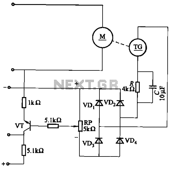
The capacitor C is part of the speed differential negative feedback system. The adjustment potentiometer RP allows for changing the amount of negative feedback. Both components can be utilized simultaneously within the circuit. The voltage (or speed) will only...
If an oscillator of a specific frequency and mark-to-space ratio is needed, the periodic time can be calculated from the required frequency, as well as the discharge and charge times using the formulas for tD and tC outlined in...