
High Volt LED Flasher

The flasher circuit operates by converting alternating current (AC) into a pulsed output that generates visible flashes of light. The circuit typically consists of a few key components: a DIAC, a resistor, a capacitor, and a light-emitting diode (LED) or another type of lamp.
When the AC voltage is applied, the capacitor begins to charge through the resistor. Once the voltage across the capacitor reaches the breakover voltage of the DIAC, the DIAC conducts and allows current to flow through the load—typically an LED. This causes the LED to flash brightly. After the capacitor discharges, the DIAC turns off, cutting off the current flow, and the cycle repeats, resulting in a flash rate of approximately one flash per second.
The choice of resistor and capacitor values is crucial, as they determine the charging time of the capacitor and thus the flash rate. For instance, a larger capacitance or resistance will slow down the charging process, leading to a longer flash interval, while smaller values will speed it up. The circuit is efficient and straightforward, making it suitable for various applications, including decorative lighting and signaling devices.
Overall, this flasher circuit design effectively utilizes AC power to create a visually appealing flashing effect, with the DIAC playing a pivotal role in controlling the timing of the flashes.Here is a Flasher circuit that directly derives power from AC to give brilliant flashes at the rate of one flash per second. It uses a Diac as the main ele. 🔗 External reference
Related Circuits

This circuit is essentially a classic buck regulator that utilizes a TMOS N-channel power FET for the chopper and generates its own supply for gate control. The unique feature of this circuit is its method for creating a separate...
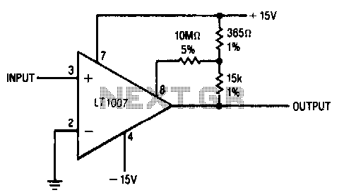
Positive feedback to one of the nulling terminals creates approximately 5 μV of hysteresis. The output can sink 16 mA; the input offset voltage is typically changed to less than 5 μV because of the feedback. In this circuit, the...
This circuit is an adjustable voltage reference circuit, which serves as a voltage source that provides a voltage greater than that of the reference diode. High precision applications that operate over an extended temperature range necessitate a restriction on...
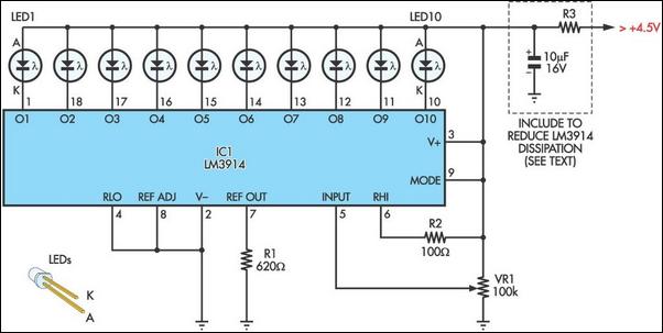
This design is directly derived from the manufacturer's datasheets, but its application is relatively novel. Initially intended for high-visibility LED bargraph readouts, the LM3914 is utilized here as the foundation for a 10-step variable brightness current-regulated white LED torch....
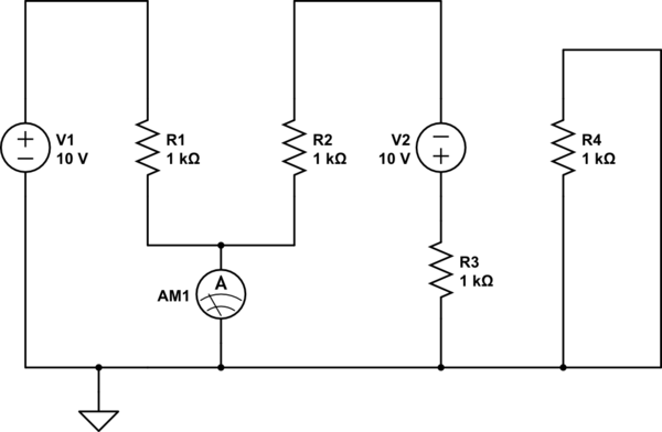
There is one significant low-impedance node in the entire circuit, referred to as 0V, located at the frame and the intersection in the middle. The upper voltage source is connected to this midpoint through a 1kΩ resistor, indicating that...

The L296 chip is a high-current switching power supply component designed to operate within a voltage range of 5 to 15V and provide an output current of up to 4A. This monolithic chip incorporates several features including enhanced protection...