
Mathematical approch to measuring current voltage and resistance of mixed series and parallel

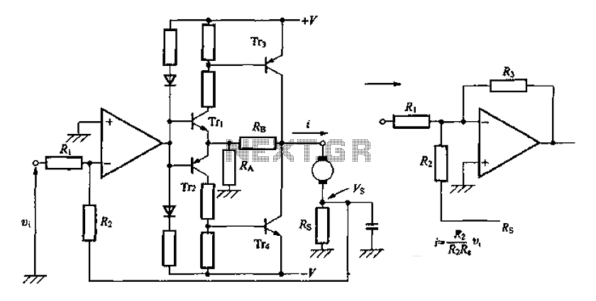
The circuit features a low-impedance node that plays a crucial role in defining the reference point for the entire system. This node, designated as 0V, serves as a common ground for the circuit's operation. The connection of the upper voltage source to this node through a 1kΩ resistor establishes a pathway for current flow, enabling the lower voltage source to exert its influence over the circuit dynamics.
The two resistors positioned in the upper half of the circuit form a potential divider. In a potential divider configuration, the voltage across each resistor is determined by the ratio of their resistances. While it might initially appear that both sides of the divider are at 0V, the active voltage generation from the upper source alters this perception. The upper voltage source, supplying 5V, elevates the potential on its side of the divider, while the lower voltage source, at -5V, pulls the potential down on the opposite side.
This configuration creates a balanced yet dynamic voltage distribution across the circuit. It is essential to consider the effects of these voltage levels on the overall circuit behavior, particularly in applications where precise voltage references are critical. The interaction between the upper and lower voltage sources, mediated by the resistive components, establishes a stable operating environment for connected devices or circuits, ensuring reliable performance across a range of operational conditions.There is one important low-impedance node in the whole circuit. That`s the frame and the cross in the middle. Let`s call that 0v. The top voltage source is connected to the middle via that 1k resistor, that means the lower voltage source has priority. the two resistors in the top half form a potential divider between 0v and 0v, so you might think of the top voltage source as sitting at about 0v too. However, since it`s generating a voltage, then the top side will be at 5v, and the bottom side at -5v. 🔗 External reference
Related Circuits
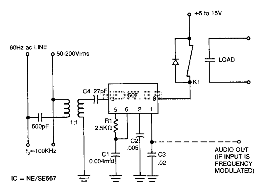
Carrier current remote control device or intercom circuit diagram as follows: The circuit diagram for a carrier current remote control device or intercom system typically involves the use of carrier current technology to transmit audio signals over existing electrical...
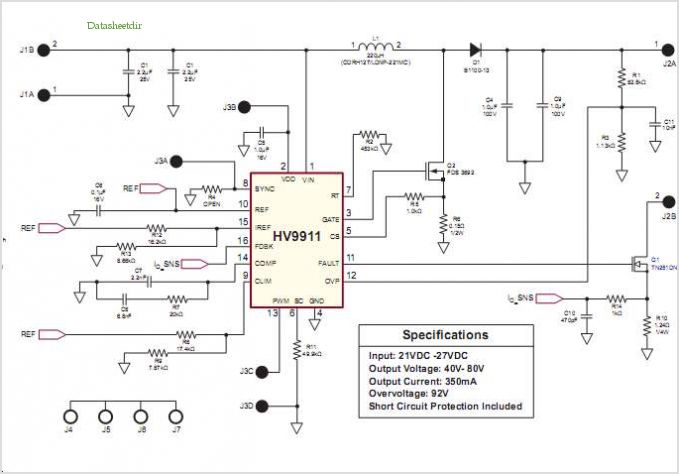
Conventionally, a MOSFET with a voltage rating of 1500V or a Half-Bridge configuration utilizing two MOSFETs rated at 800-900V is employed for Switch Mode Power Supply (SMPS) applications that require input voltages exceeding 380Vac. However, these methods present challenges,...
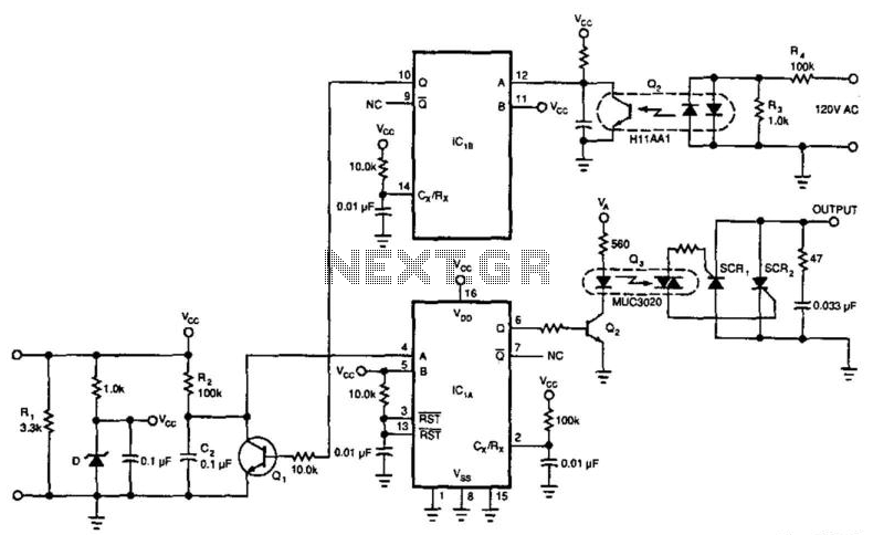
This circuit enables a 4-to-20 mA current loop to control an isolated SCR drive. IC1A and IC1B function as one-shot timers. Q2 detects zero crossings of the 120 Vac line, which triggers one-shot IC1B. IC1A causes Q1 to discharge...
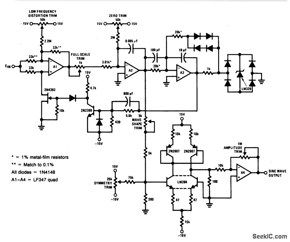
For a 0- to 10-V input, this circuit generates sine-wave outputs ranging from 1 Hz to 20 kHz, achieving linearity better than 0.2%. The distortion level is approximately 0.4%, and both the frequency and amplitude of the sine-wave output...
This is a simple circuit of a Positive Voltage Doubler. This circuit utilizes the MAX1044/ICL7660. The Schottky diode was selected to reduce the voltage drop. The Positive Voltage Doubler circuit is designed to convert a lower input voltage into a...
A discrete transistor current control circuit diagram. The discrete transistor current control circuit is designed to regulate the flow of current through a load by utilizing a transistor as the primary control element. This circuit typically consists of a few...