
High voltage power supply
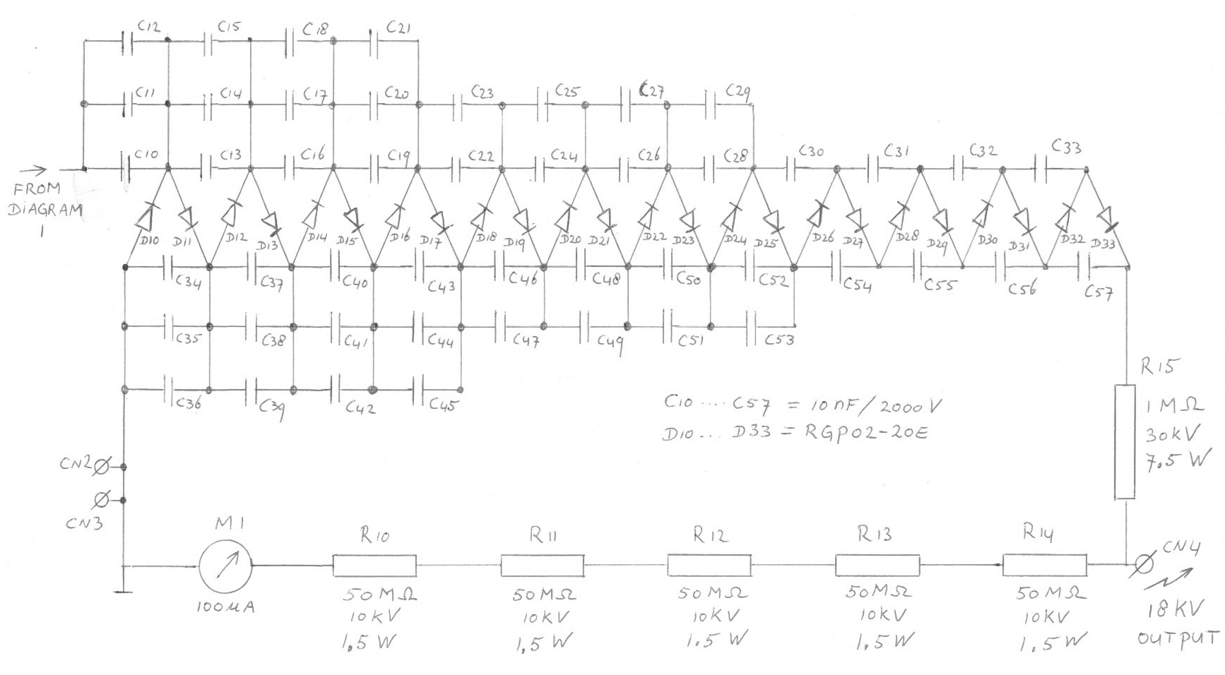
The described circuit appears to be a high-voltage cascade generator, commonly used in applications requiring significant voltage amplification. The cascade consists of 12 stages, each contributing an incremental voltage of 1700 volts. The total theoretical output voltage, when all stages are operational and unloaded, amounts to over 20 kV.
In practical applications, this type of circuit is often used in particle accelerators, X-ray machines, or other devices where high voltage is necessary. The design typically incorporates a series of capacitors and transformers that step up the voltage stage by stage. Each stage operates under the principle of voltage multiplication, where the output of one stage serves as the input for the next.
It is important to note that the specified output voltage can only be attained under unloaded conditions. When a load is connected to the output, the voltage will drop significantly due to the load's impedance and the internal resistance of the cascade stages. Proper design considerations must be taken into account to ensure stability and performance under varying load conditions.
Safety precautions are critical when working with high-voltage circuits to prevent electrical hazards. Insulation, clearances, and protective equipment must be employed to safeguard against accidental contact with high-voltage components. Additionally, the circuit should be designed to handle potential voltage spikes and transient responses effectively.
Overall, the high-voltage cascade generator is an essential component in various high-energy applications, and careful design and implementation are necessary to achieve the desired performance and safety standards.Every next stage is adding 1700 Volts, so with 12 stages we get more then 20 kV, this voltage can however only be reached when the output of the cascade is not loaded. 🔗 External reference
Related Circuits
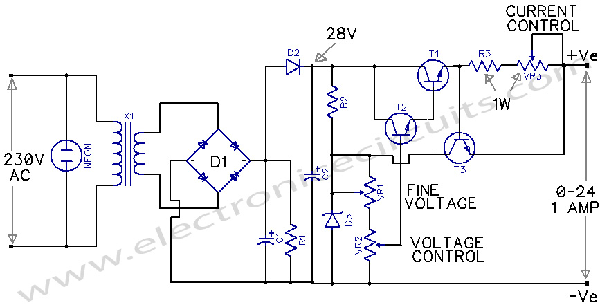
The circuit presented is an economical smooth variable power supply that offers an output range from 0V to 24V. It includes all necessary controls and features protection against short circuits. This variable power supply circuit is designed to provide a...
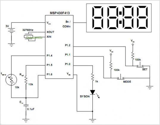
More: A comprehensive electronic schematic that outlines the design and functionality of a specific circuit is crucial for understanding its operation. The schematic should include components such as resistors, capacitors, diodes, transistors, and integrated circuits, along with their interconnections....

Sometimes referred to as the JFET µ-amp, this circuit offers a very low power, high gain amplification function. As the drain current decreases, the µ of a JFET increases, meaning that the lower the drain current, the greater the...
As mentioned in the chapter about the DAC, this circuit shifts the voltage output range. The following diagram explains its operation and structure. The circuit's outputs are connected to the input pins of the power operational amplifiers. The described circuit...
This is a regulated and adjustable power supply that can deliver up to 20A with an adjustable voltage range between 4V and 30V. It is straightforward to construct and utilizes the LM338 voltage regulator. The adjustable power supply circuit based...
This circuit primarily relies on a voltage regulator. The 7809 voltage regulator can provide a continuous output of up to 2 amps while ensuring a low noise and highly regulated supply. Although the circuit can function without additional components,...