
Ultra-high gain audio amplifier

The JFET µ-amp circuit utilizes a Junction Field Effect Transistor (JFET) to achieve its amplification characteristics. The JFET operates by controlling the current flow through a semiconductor channel via an electric field created by the gate voltage. This configuration allows for high input impedance and low output impedance, making it suitable for various applications where signal integrity is critical.
The gain of the JFET amplifier can be adjusted by varying the drain current. A lower drain current results in a higher transconductance (µ), which directly translates to increased voltage gain. However, this increase in gain comes at the cost of input dynamic range, as the circuit may become more sensitive to noise and distortion at higher gain levels.
In practical applications, the JFET µ-amp is often used in sensor signal conditioning, audio amplification, and other low-power applications where high gain is required without introducing significant power consumption. The circuit design typically includes biasing resistors to stabilize the operating point of the JFET, ensuring consistent performance across varying temperatures and supply voltages.
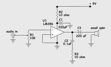
Overall, the JFET µ-amp circuit is a versatile and efficient solution for applications requiring high gain with minimal power usage, though careful consideration must be given to the trade-offs in input dynamic range as gain is maximized.Sometimes called the JFET µ-amp, this circuit provides a very low power, high gain amplifying function. Since µ of a JFET increases as drain current decreases, the lower drain current is, the more gain you get
Input dynamic range is sacrificed with increasing gain, however.
Related Circuits
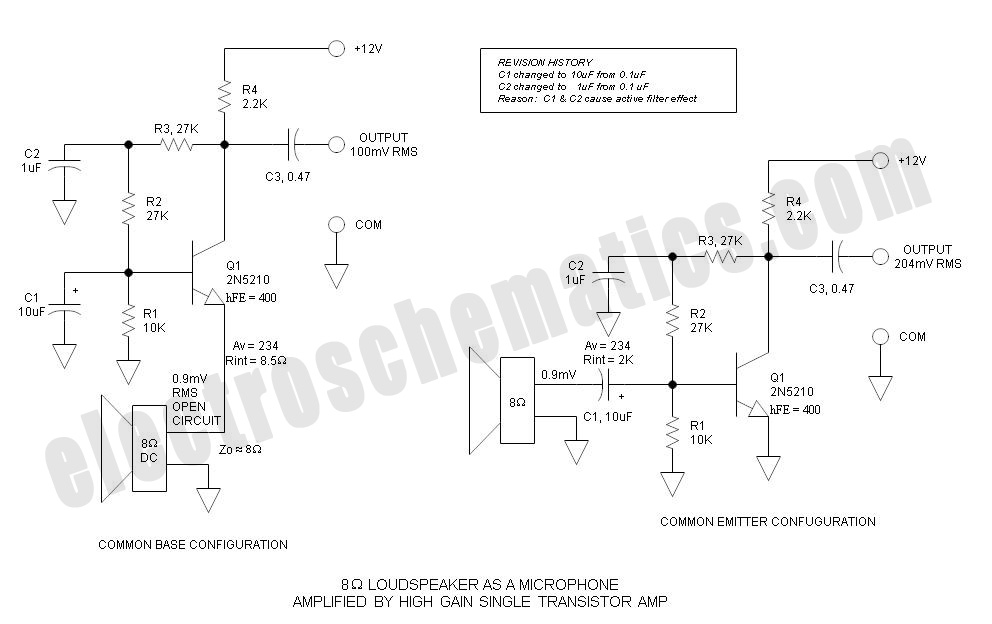
Single Transistor Amplifier Revisited Part 3, Common Base vs Common Emitter Configuration, Update One nagging question that I have long had is this: How do... The single transistor amplifier is a fundamental building block in electronic circuits, and its configurations—common...
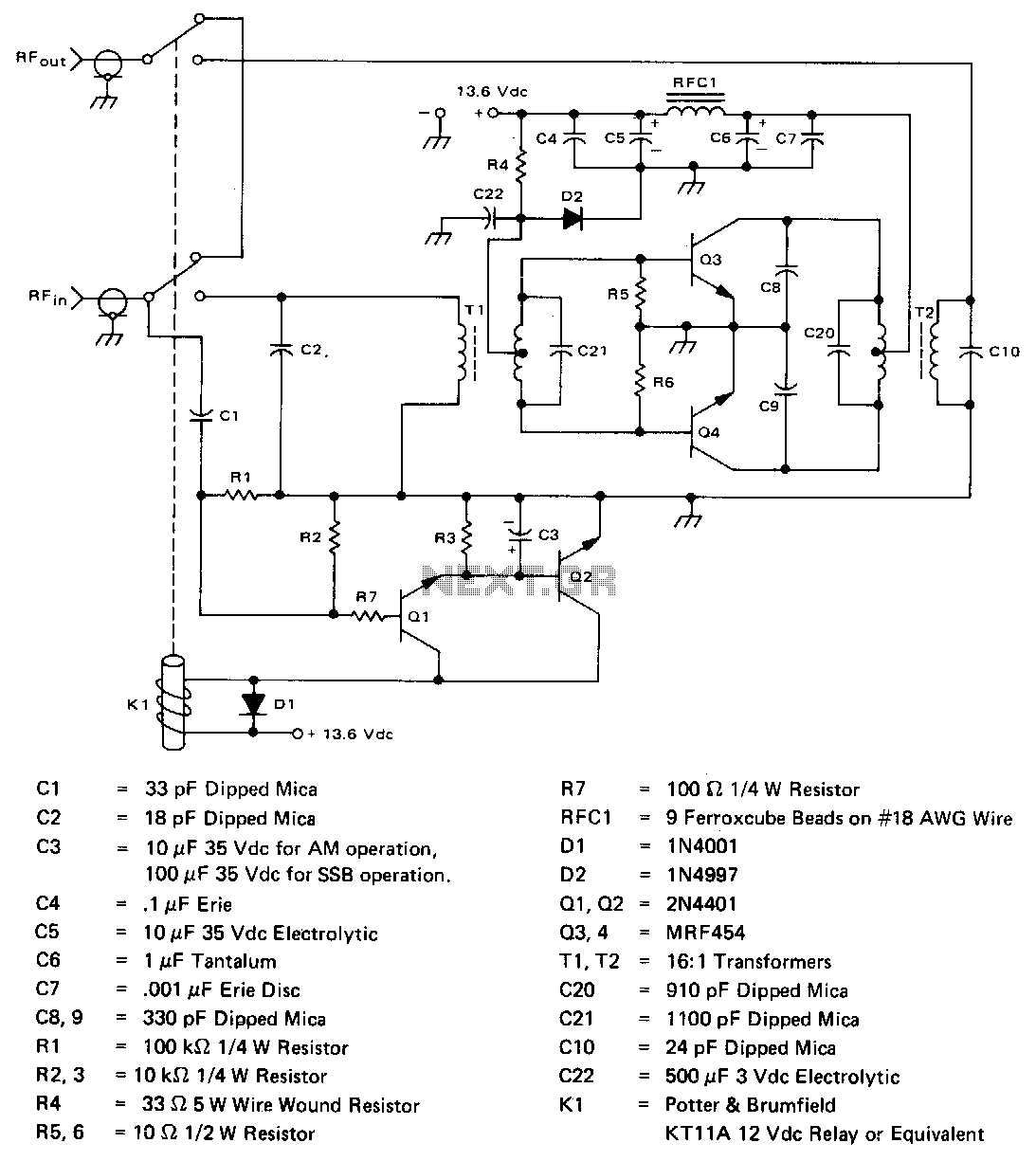
The amplifier operates across the 2-30 MHz band with a relatively flat gain response and reaches gain saturation at approximately 210 W of output power. Both input and output transformers have a 4:1 turns ratio (16:1 impedance ratio) to...

A photodiode can be utilized for high-speed digital transmission; however, it is necessary to provide a high-speed signal conditioner for this purpose. The amplifier circuit... A photodiode is a semiconductor device that converts light into electrical current. In high-speed digital...
This solid-state push-pull single-ended Class A circuit is designed to deliver sound quality comparable to valve amplifiers, providing an output power of 6.9W measured across an 8 Ohm loudspeaker cabinet load. It features reduced total harmonic distortion (THD), increased...
In the circuit exists a simple power amplifier 60W in the 8 ohm and 80W in the 4 ohm, with components that sure exist in big quantities. It can be used in home cinema systems or in other uses....
The schematic diagram presented is of a twin "T" phase shift oscillator, an audio oscillator. This oscillator derives its name from the phase shift network formed by resistors R3, R4, and capacitors C1, C2, and C3. This network shifts...