
High voltage speed optocoupler and application circuit diagram

High-speed optocouplers are essential components in modern electronic systems, especially in applications requiring efficient isolation and signal transfer across different voltage domains. The rise time of less than or equal to 300 ns indicates the rapid response of these devices, making them suitable for high-frequency applications. The circuit transfer ratio of 50% signifies that the output signal strength is half of the input signal strength, which is adequate for many control and feedback applications.
The isolation voltage rating of at least 15,000 V ensures that the optocoupler can safely operate in high-voltage environments without risk of breakdown or signal interference between the high-voltage and low-voltage sides. The reverse breakdown voltage of at least 50 V for the output transistor further enhances the reliability of the optocoupler in circuits where transient voltages may occur.
In high-voltage regulator circuits, these optocouplers play a critical role by providing feedback from the output to the input circuit, allowing for precise regulation of voltage levels while maintaining electrical isolation. This isolation is crucial for protecting sensitive low-voltage components from high-voltage spikes or noise, thereby ensuring the integrity and stability of the entire system.
The requirement for a +27 V DC power supply on the high-pressure side, which must exceed 15 kV, indicates the need for careful design considerations in power management and safety measures. This independent power supply arrangement helps maintain the necessary voltage levels for proper operation while minimizing the risk of interference or damage to the low-voltage side of the circuit.
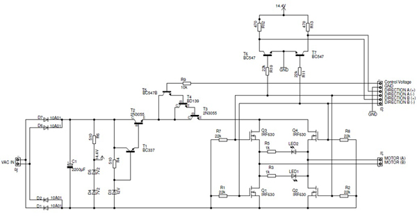
Overall, high-speed optocouplers are indispensable in applications where high-voltage isolation, rapid signal transfer, and reliable feedback mechanisms are necessary for the effective operation of electronic systems.High speed optocouplers technical parameters are: Rise time t1 ‰¤ 300ns; Circuit eye transfer ratio CTR = 50%; Isolation voltage VSO ‰¥ 15000V; Output transistor reverse breakdown voltage V (BR) CEO ‰¥ 50V. The optical coupler can be widely used for the high-voltage isolators, high-voltage pulse transformers and high-voltage power circuit voltage stability control system.
T he control systems is used for high voltage regulator circuit. The fast high-voltage electrical coupling in this circuit play two roles. First one is to achieve the output voltage feedback loop in the input circuit and high voltage isolation between the low-voltage circuits; The other role is to achieve high output voltage feedback signal. Note: The high pressure side +27 V DC power supply is independent, but its pressure level must be greater than 15KV.
🔗 External reference
Related Circuits
The integrated circuit input side contains an oscillating circuit, where the oscillation frequency is determined by the external components L1, C1, and the sensor's equivalent capacitance. The equivalent capacitance increases as the sensor is immersed in liquid. The oscillating...

This topic will be locked and will display all of the circuits and some photos of the devices being worked on in the Joule Thief topic. This process will take some time, so patience is appreciated. If any errors...
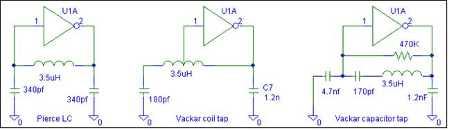
This oscillator does not require biasing components. Only an inductor and various matching or tuning capacitors are needed to set the operating frequency. The active component is the 74HCU04 hex inverter, with only one of the six inverters necessary...
Most of the power supply failure indicator circuits need a separate power supply for themselves. But the alarm circuit presented here needs no additional supply source. It employs an electrolytic capacitor to store adequate charge, to feed power to...
This circuit is a small +5V power supply, which is useful when experimenting with digital electronics. Small inexpensive wall transformers with variable output voltage are available from any electronics shop and supermarket. Those transformers are easily available, but usually...
The K8000 DAC High Power Amplifier is an electronic amplifier with an adjustable output voltage ranging from 0 to 9 V and capable of delivering an output current of up to 9 Amperes. The K8000 DAC High Power Amplifier is...