
Simple 5V power supply for digital circuits

The described circuit functions as a regulated +5V power supply, suitable for powering various digital electronics projects. It typically incorporates a transformer, a rectifier, a filter capacitor, and a voltage regulator to provide stable output voltage.
1. **Transformer**: The circuit begins with a small wall transformer that steps down the AC mains voltage to a lower AC voltage. The output voltage of the transformer is selected based on the required input for the subsequent components, generally in the range of 7V to 9V AC to allow for adequate headroom for regulation.
2. **Rectifier**: The AC voltage from the transformer is then fed into a rectifier circuit, which can be a full-wave bridge rectifier composed of four diodes arranged in a bridge configuration. This converts the AC voltage into pulsating DC voltage. The choice of diodes should be based on the current rating and reverse voltage requirements of the application.
3. **Filter Capacitor**: Following the rectifier, a large electrolytic capacitor is used to smooth the pulsating DC output into a more stable DC voltage. This capacitor charges during the peaks of the rectified voltage and discharges during the troughs, thereby reducing ripple voltage and providing a more constant output.
4. **Voltage Regulator**: The smoothed DC voltage is then fed into a voltage regulator, commonly a linear regulator such as the 7805, which outputs a steady +5V. This component is crucial for ensuring that fluctuations in input voltage do not affect the output voltage, making it suitable for sensitive digital circuits. The regulator typically requires additional capacitors on its input and output to stabilize the voltage and improve transient response.
5. **Output**: The final output of the circuit provides a clean +5V DC voltage suitable for powering microcontrollers, logic circuits, and other digital devices.
Additional considerations include the heat dissipation of the voltage regulator, which may require a heatsink if the load current is significant. It is also advisable to include fuses or circuit protection components to safeguard against overcurrent conditions. Overall, this circuit design addresses the common challenges associated with using unregulated wall transformers in digital electronics experimentation.This circuit is a small +5V power supply, which is useful when experimenting with digital electronics. Small inexpensive wall tranformers with variable output voltage are available from any electronics shop and supermarket.
Those transformers are easily available, but usually their voltage regulation is very poor, which makes then not very usable for digital circuit experimenter unless a better regulation can be achieved in some way. The following circuit is the answer to the problem. 🔗 External reference
Related Circuits
The circuit involves powering an LED using a 3V CR2032 battery, with the intention of extending battery life by making the LED blink rather than remain continuously on. A 555 timer is considered, utilizing large value resistors in the...
The first two components are passive elements, while the operational amplifier (op-amp) is an active element. The passive elements are two-terminal components, whereas the op-amp is a three-terminal component. A resistor controls the current flowing through it when a...
The purpose of this timer is to disconnect the compressor circuit and connect a resistive heating element located near the evaporator at regular time intervals. The defrost heater is controlled by a thermostat and is used to melt any...

Usually we see Digital clock on LCD or 7 segment. But, this AVR Digital Clock which is designed by Ficara Emilio displayed on Oscilloscope. The project uses ATtiny 2313 as the main controller. What an interesting microcontroller project. Source...

The 78W series voltage regulators are designed to handle an input voltage of approximately 35V, while the 24V type can withstand up to 40V. It should be noted that these regulators will not operate effectively with a significant input-output...
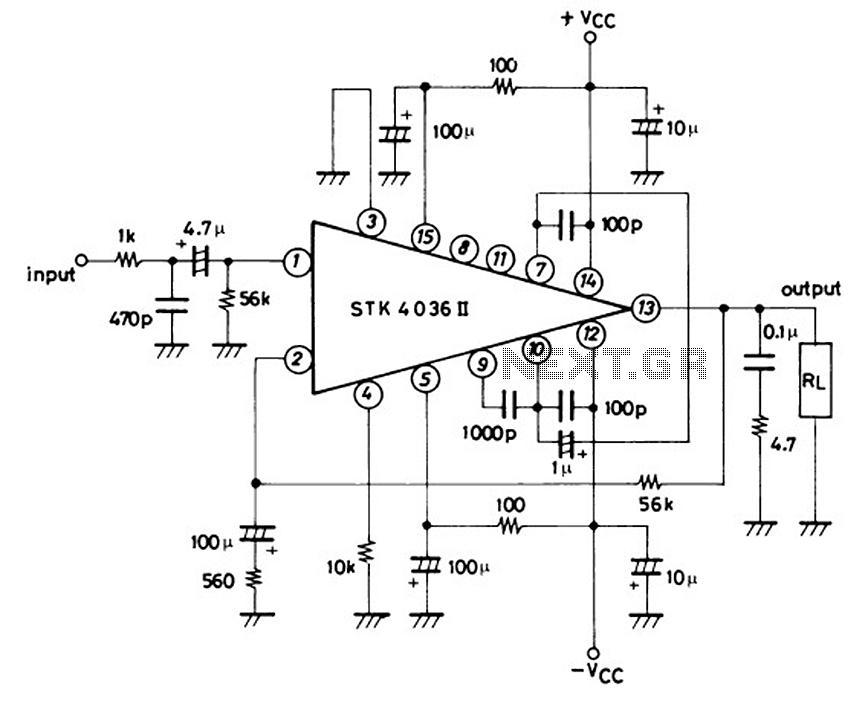
This is a 50-watt audio power amplifier circuit based on the single IC STK4036II. A heatsink is required to prevent overheating of the IC. The amplifier circuit provides good sound quality at an affordable price and is easy to...