
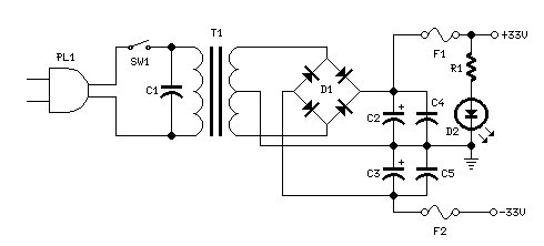
High-Voltage Supply Circuit

The circuit operates by utilizing a transistor oscillator to create a high-frequency signal, which is then used to drive a voltage multiplier circuit. This voltage multiplier consists of diodes and capacitors arranged in a manner that effectively increases the input voltage to a significantly higher level. Capacitors CIO and CI1 are charged to this elevated voltage, storing substantial electrical energy.
When the spark gap, a crucial component in this circuit, reaches its breakdown voltage, it allows the stored energy in capacitors CIO and CI1 to discharge rapidly. This discharge occurs through the primary winding of the auto ignition coil, T2. The rapid collapse of the magnetic field in the coil generates a high-voltage pulse in the secondary winding, which can be utilized to ignite fuel in an internal combustion engine or for other applications requiring a brief, high-voltage spark.
The design of this circuit is particularly effective for applications requiring ignition systems, as it can deliver the necessary high-voltage pulses reliably and efficiently. The use of an auto ignition coil as T2 ensures that the circuit can handle the high voltages involved while maintaining durability and performance over time. This circuit uses a transistor oscillator and a voltage multiplier to charge CIO and CI 1 to a high voltage. When the spark gap breaks down, T2 produces a high-voltage pulse via the capacitance discharge of CIO and Cll into its primary.
T2 is an auto ignition coil.
Related Circuits
Power supply for a 25W power amplifier based on a MOSFET design. This power supply circuit is paired with a high-power audio amplifier rated at 1500 watts. The design of the power supply for the amplifier requires careful consideration....
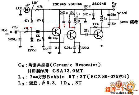
The quartz crystal oscillator circuit is highly advantageous in terms of frequency stability. Even the Voltage-Controlled Crystal Oscillator (VCXO) circuit, which allows for significant frequency changes, typically experiences only about a 1% variation. However, the linear range of control...
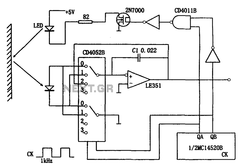
The circuit for detecting the intensity of reflected light includes infrared light-emitting diodes, photodiodes, CMOS analog switches, operational amplifiers, and other components. When the circuit operates, the infrared light-emitting diode (LED) initially remains off, allowing the photodiode to receive...
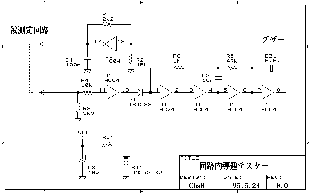
Continuity tester to check continuity in the circuit (Insakittochekka) is. The continuity check over the circuit board wiring that can be checked at a lower voltage semiconductors do not conduct contained in the circuit, you can just check the...
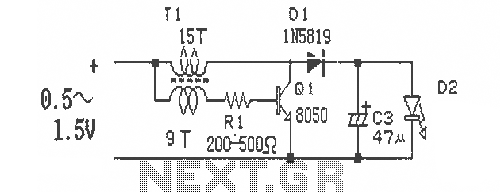
This is a simple and easy-to-build DC-DC driver circuit designed for a single flashlight battery, operating at a parametric voltage of 1.5V. The input current is 90mA, while the light-emitting diode (LED) current is 26mA or higher. The circuit...
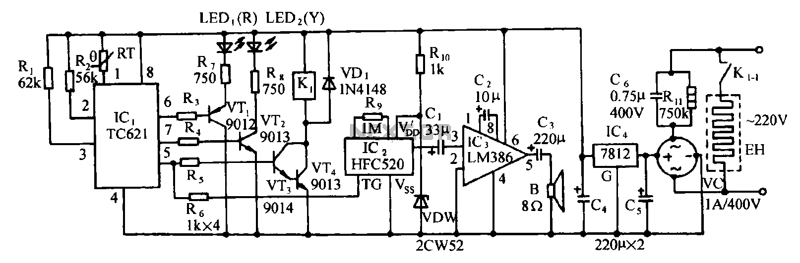
Eggs hatch chicks at temperature requirements within the range of 36 to 39 degrees Celsius. The temperature sensor integrated circuits utilize the TC621 temperature control circuit, which has fewer external components, is low cost, and offers high reliability. Users...