
Continuity in Circuit Tester

The continuity tester circuit is designed to assess the integrity of electrical connections within a circuit board. It operates effectively at lower voltages, ensuring that semiconductors, which typically do not conduct at these levels, can be evaluated without causing damage. The primary function of this tester is to identify short circuits and verify that unaffected components remain operational.
The schematic for the continuity tester incorporates both digital integrated circuits (ICs) and analog components. The input threshold is set at 1/2Vcc, which allows the circuit to function optimally within its designed voltage range. The output voltage is maintained at approximately 1.7V, which is crucial for providing feedback to the inverter stage of the circuit. This feedback mechanism ensures that the inverter operates correctly, allowing for accurate continuity testing.
The circuit is capable of measuring voltage drops as low as 0.2V. When the voltage at the input exceeds 1.5V, the circuit activates an oscillator that drives a buzzer, providing an audible indication of continuity. The semiconductor components in the circuit typically exhibit a voltage drop ranging from 0.5V to 0.6V during conduction, which is a critical parameter for assessing the performance of the circuit.
Furthermore, the continuity tester is designed to detect pure resistance below 500 ohms, indicating that connections are solid and without significant resistance that could lead to circuit failure. This feature is essential for ensuring that all components within the circuit board are functioning correctly and that there are no interruptions in the electrical pathways.Continuity tester to check continuity in the circuit (Insakittochekka) is. The continuity check over the circuit board wiring that can be checked at a lower voltage semiconductors do not conduct contained in the circuit, you can just check the wiring short miscarriage pure unaffected parts. Schematic that I'll know to take a look and are used in digital IC and analog operation. First, using Input Threshold 1/2Vcc to become, over the output voltage to approximately 1.7V feedback to keep the inverter, and output it. Circuit to measure voltage drop of 0.2V or less, the voltage of 1.5V and above the recipient, the buzzer will sound running oscillator.
The conduction of the semiconductor ring because the voltage drop to around 0.5 ~ 0.6V. If the sound is pure resistance below 500?. 🔗 External reference
Related Circuits
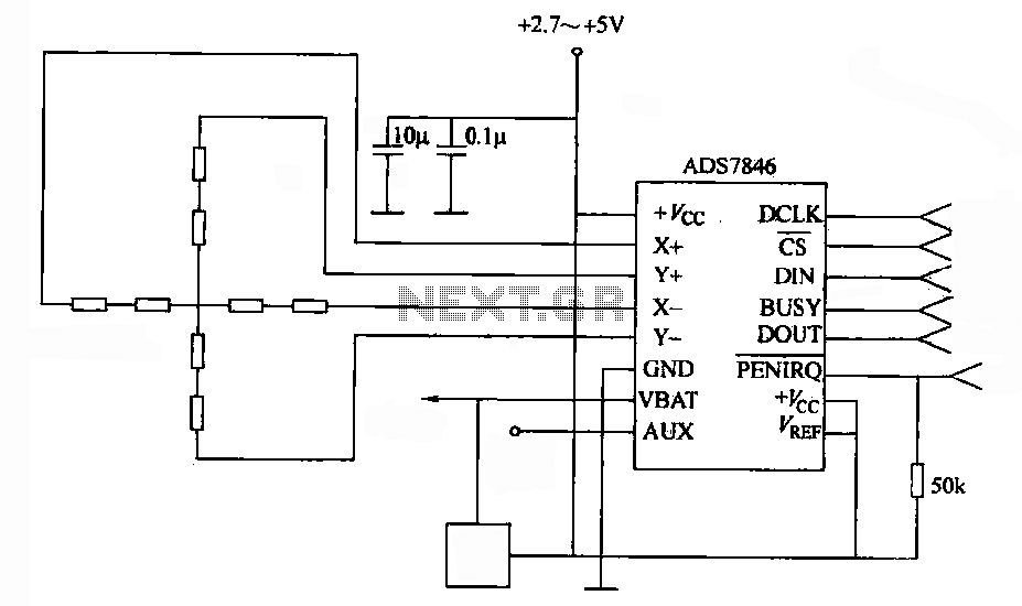
A 4-wire resistive touch screen utilizes an ADS7846 interface circuit. The ADS7846 analog chip incorporates electronic switches and a successive approximation A/D converter. The analog switch chip controls the switching of the X+ (or Y+) positive supply terminal, while...
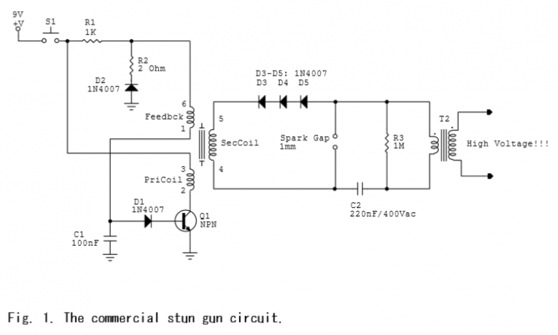
A commercial stun gun circuit that generates approximately 100 kV pulses from a 9V battery is illustrated in Figures 1-2. The core of the circuit is a power oscillator centered around transistor Q1. When switch S1 is activated, capacitor...
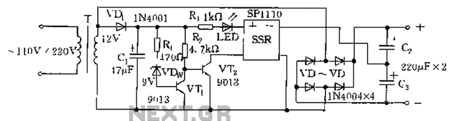
The circuit is automatically converted to a low-voltage configuration. A 220V AC supply is stepped down by transformer T. After this, the breakdown voltage of diode VDw causes transistors VT1 and VT2 to turn off, resulting in the solid-state...
This circuit utilizes an LM339 quad voltage comparator to create a time delay and manage a high current output at low voltage levels. Approximately 5 amps of current can be achieved using two fresh alkaline D batteries. Three of...
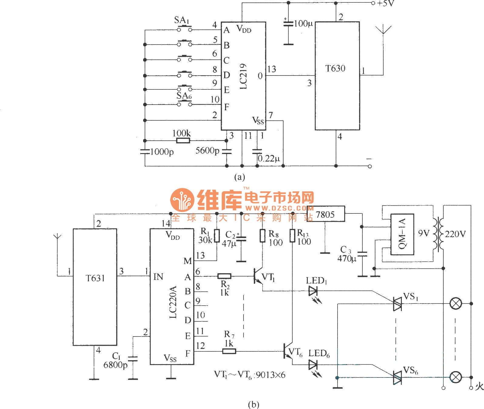
The circuit utilizes the long-wave wireless transceiver T630/T631 to manage a 6-channel load. It is characterized by low power consumption, high resistance to interference, and a simple structure. The circuit design incorporates the T630/T631 transceiver, which operates in the long-wave...

The AC contactor operates silently, demonstrating significant energy-saving effects, low noise, and a reduced operating temperature, which contributes to an extended lifespan. It is widely utilized in the production industry. When the SB2 button is pressed, the N-terminal receives...