
High voltage switching stabilized voltage supply circuit

The high voltage switching stabilized voltage supply circuit is designed to efficiently convert and regulate voltage for electronic devices, particularly for color televisions of the 80P type. At the core of this circuit is a PWM (Pulse Width Modulation) controller that manages the switching of the power transistors. This method allows for precise control over the output voltage and minimizes power loss, enhancing overall efficiency.
The circuit begins with a power frequency rectification and filtration stage, which converts the incoming AC voltage into a smoother DC voltage. This is crucial for ensuring that the subsequent stages of the circuit receive a stable input. The rectification is typically achieved using a bridge rectifier configuration, which consists of four diodes arranged to efficiently convert both halves of the AC waveform into DC.
Following the rectification, the filtration circuit employs capacitors to reduce ripple voltage, ensuring that the output is as stable as possible. This stable DC voltage is then fed into the PWM circuit, which modulates the duty cycle of the switching transistors. The auto-excitation feature allows the circuit to self-regulate, adjusting the PWM signal based on the load conditions, which helps maintain the desired output voltages of 110V and 18V DC.
The isolation of the output from the power system is a critical safety feature. It prevents any direct electrical connection between the high voltage supply and the input power, reducing the risk of electric shock and ensuring compliance with safety standards. This isolation is typically achieved using transformers or opto-isolators, which serve to separate the control and power sections of the circuit.
In summary, this high voltage switching stabilized voltage supply circuit is a sophisticated design that integrates modern switching technology with traditional rectification and filtration methods. It provides reliable and isolated voltage outputs necessary for the operation of color televisions, demonstrating the importance of efficiency and safety in electronic power supply design.High voltage switching stabilized voltage supply circuit is shown in the diagram. It is the switching power supply of 80P type color TV. It adopts auto-excitation, PWM circuit. Its output is isolated with power system. This power supply has 110V and 18V DC voltage output. The power supply consists of power frequency rectification filtration circuit, start os.. 🔗 External reference
Related Circuits
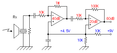
The ultrasonic signal received by the reception sensor is amplified by a factor of 1000 (60 dB) using a two-stage operational amplifier. The first stage provides a gain of 100 (40 dB), while the second stage offers a gain...
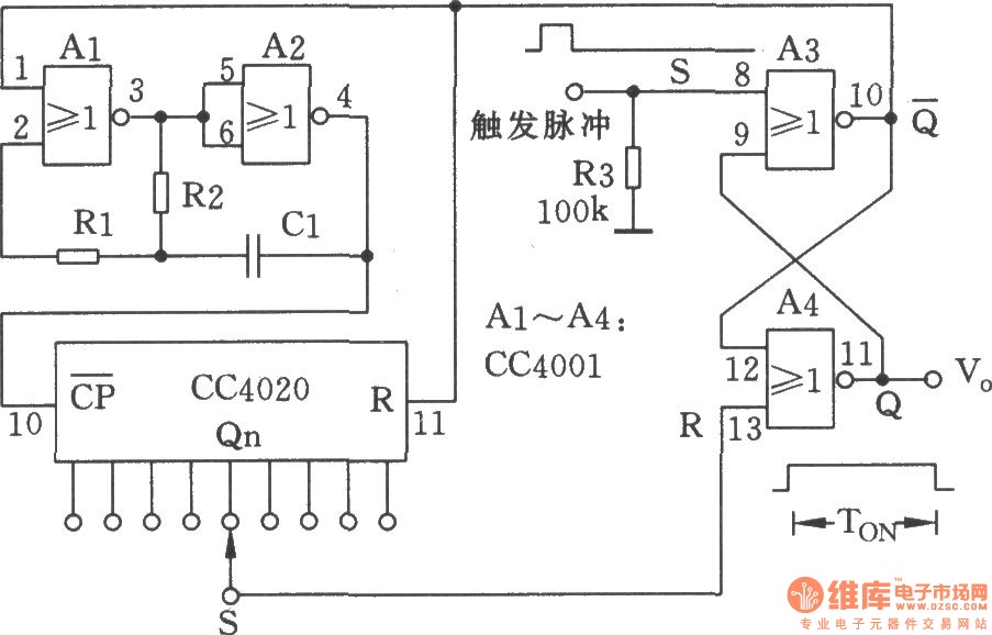
The NC monostable multivibrator circuit depicted in the chart consists of four 2-input NOR gates (CC4001) and a 14-bit binary serial counter/divider (CC4020). It is primarily utilized as a time delay switch or timer in automatic control equipment. The NC...
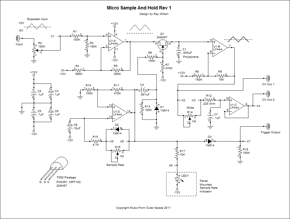
The voltage to be sampled is applied to the input of R2, a 100K linear taper potentiometer, while the other end of R2 is grounded. Consequently, the signal level that is sent to the buffering level shifter U1-A and...
Four observations regarding the Joule Thief AA battery LED circuit. The schematic of the LED circuit illustrates the power source (V1), which symbolizes a depleted battery with only 1 volt remaining and an internal resistance. The Joule Thief circuit is...
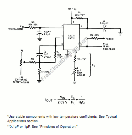
A voltage-to-frequency converter can be constructed using the LM231/331 chip, making it a cost-effective solution for applications such as analog-to-digital conversion and frequency-to-voltage conversion over extended periods. The LM231/331 series of voltage comparators can be effectively utilized to design a...
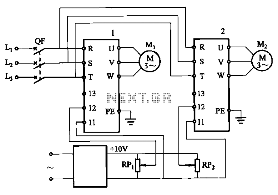
Adjust the potentiometers RPi and RPz to modify the speed of two motors. The circuit utilizes two potentiometers, designated as RPi and RPz, to control the speed of two separate motors. Each potentiometer is connected in a voltage divider configuration,...