
Circuit explanation for Ultrasonic Range Meter

The circuit design described integrates several key components that work together to amplify and process ultrasonic signals effectively. The operational amplifier stages provide significant amplification, ensuring that even weak signals can be detected accurately. The use of a single power supply simplifies the design while still allowing for effective biasing, which is critical for maintaining signal integrity. The half-wave rectification circuit, utilizing Schottky diodes, ensures that high-frequency signals are processed efficiently, minimizing signal loss and distortion.
In addition, the integration of a holding circuit using an SR flip-flop allows for stable signal detection, preventing false readings during the transmission pulse. The control logic implemented through the PIC microcontroller ensures precise timing and accurate detection of reflected signals, enhancing the overall reliability of the ultrasonic sensing system. This combination of amplification, rectification, and digital processing yields a robust solution for ultrasonic signal detection, suitable for various applications in measurement and sensing technologies.The ultrasonic signal which was received with the reception sensor is amplified by 1000 times(60dB) of voltage with the operational amplifier with two stages. It is 100 times at the first stage (40dB) and 10 times (20dB) at the next stage. Generally, the positive and the negative power supply are used for the operational amplifier. The circuit thi s time works with the single power supply of +9 V. Therefore, for the positive input of the operational amplifiers, the half of the power supply voltage is appied as the bias voltage. Then the alternating current signal can be amplified on 4. 5V central voltage. When using the operational amplifier with the negative feedback, the voltage of the positive input terminal and the voltage of the negative input terminal become equal approximately.
This is called virtual grounding. So, by this bias voltage, the side of the positive and the side of the negative of the alternating current signal can be equally amplified. When not using this bias voltage, the distortion causes the alternating current signal. This technique is often used when using the operational amplifier which needs two kinds of powers in the single power.
The detection is done to detect the received ultrasonic signal. This is the half-wave rectification circuit with Shottky barrier diodes. The DC voltage according to the level of the detection signal is output to the capacitor behind the diode. The Shottky barrier diodes are used because the high frequency characteristic is good. This circuit is the circuit which detects the ultrasonic which returned from the measurement object. The output of the detection circuit is detected using the comparator. At the circuit this time, the operational amplifier of the single power supply is used instead of the comparator.
The operational amplifier amplifies and outputs the difference between the positive input and the negative input. In case of the operational amplifier which doesn`t have the negative feedback, the output becomes the saturation state by a little input voltage.
Generally, the operational amplifier has over 10000 times of mu factors. So, when the positive input becomes higher a little than the negative input, the difference is tens of thousands of times amplified and the output becomes the same as the power supply almost. (It is the saturation state) Oppositely, when the positive input becomes lower a little than the negative input, the difference is tens of thousands of times amplified and the output becomes 0 V almost.
(It is in the OFF condition) This operation is the same as the operation of the comparator. However, because the inner circuit of the comparator is different from the operational amplifier, the comparator can not be used as the operational amplifier. At the circuit this time, the output of the detection circuit is connected with the positive input of the signal detector and the voltage of the negative input is made constant.
This is the holding circuit of detected signal. SR ( Set and Reset ) flip-flop is used. For the details of SR-FF, refer to " The operation explanation of the D-type flip-flop ". The detector is made to be not operate in the constant time(About 1. 5 milliseconds) after sending out a transmission pulse to prevent from the wrong detection which is due to the influence of the transmission pulse. This operation is controlled with the software of PIC. When using the capture feature of PIC, this circuit isn`t indispensable. Capture operation is done by the change of the capture input in the once. The reason why I am using this circuit is to confirm signal detection operation within the reflected signal detection time(About 65 milliseconds).
When sending out next ultrasonic pulse, the output of this circuit is checked. And when the output is L level, an error display is done because the reflected signal could not be detected. The inverter is used for the drive of the ultrasonic se 🔗 External reference
Related Circuits
It is recommended to have a fuse in the power line and to always have a load connected while power is being applied. The fuse should be rated at 10 amps per 100 watts of output. The power leads...
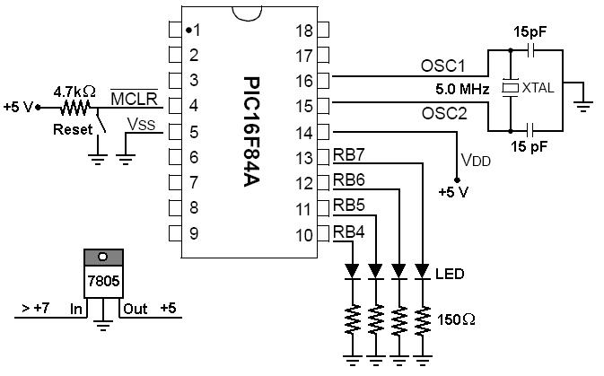
To start working with microcontrollers, several essential items are required. The PICSTART Plus kit, part number DV003001, was purchased from Microchip. This kit contains a sample PIC16F84 microcontroller chip, which in this case is a PIC16F84A chip. This chip...
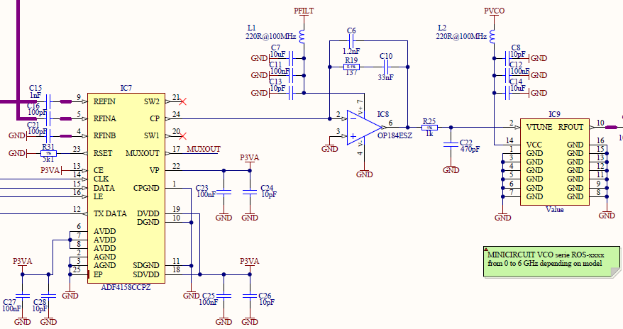
At the 10 MHz fundamental frequency, the HP8562E phase noise floor indicates that the TCXO phase noise is superior to the spectrum analyzer's noise floor. Harmonics have been measured from 20 MHz to 1 GHz, with detectable harmonics extending...
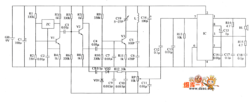
The metal detector circuit includes a fixed frequency oscillator, mixer, detector, detection oscillator, and power amplifier circuit. The fixed frequency oscillator circuit is composed of a ceramic filter (ZC), transistor (V1), resistors (R1 to R4), capacitor (C2), and other...
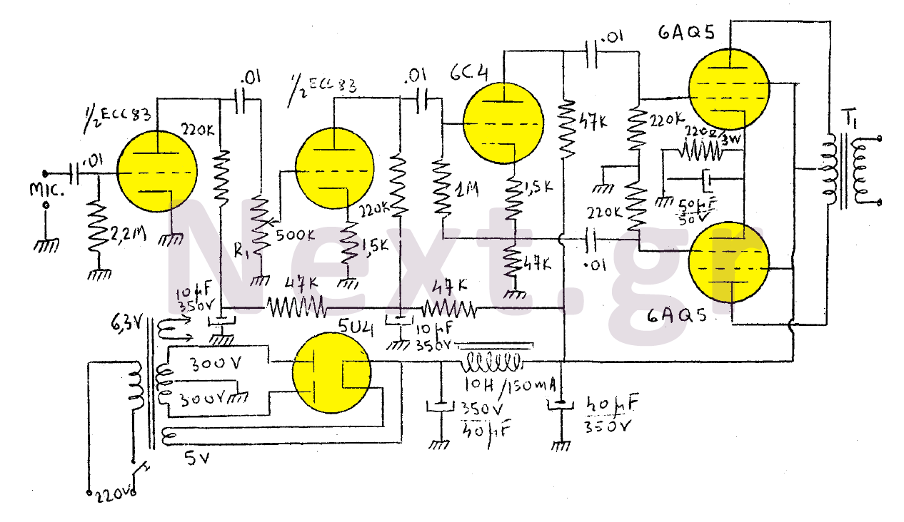
The output of this modulator consists of two 6AQ5 lamps arranged in a push-pull configuration with a maximum output of 15W. A 6C4 lamp is employed as a reversing lamp. The double-stage ESC83 serves as the pre-amplifier. The potentiometer...
Beginner's Tutorial 1: Building a Circuit on Breadboard - how to build a simple and easy circuit on a breadboard for beginners in electronics. Learn to use an LED and a resistor. This tutorial serves as an introductory guide for...