
Homebrew tapeless camera

The project involves the integration of the nNovia QC120 A2D2 recorder with the Sony DXC-325P camera, which requires a custom circuit to facilitate communication between the two devices. The core of the system is built around the PIC16F872 microcontroller, which is well-suited for handling various input and output operations. The GPI (General Purpose Interface) control lines are utilized to manage the interaction with the nNovia recorder, ensuring that commands are sent and responses are received effectively.
The circuit design incorporates a preamplifier stage, which is essential for enhancing the audio signals before they are processed by the A2D converter. This preamp will be prototyped shortly, allowing for adjustments to be made based on performance metrics. The choice of components for the preamplifier will be critical to maintaining signal integrity and minimizing noise.
Furthermore, the design intends to leverage the A2D interfaces of the PIC microcontroller to drive an LED PPM (Peak Program Meter) or VU (Volume Unit) meter. This visual feedback mechanism will be integrated into the front panel of the enclosure, providing users with real-time information about the audio levels being processed. The implementation of this feature not only enhances usability but also aids in monitoring performance during operation.
Overall, the project aims to create a reliable and user-friendly interface between the nNovia QC120 A2D2 recorder and the Sony DXC-325P camera, with careful consideration given to the audio signal processing stages and user interface components. As the design evolves, further refinements and testing will ensure that the final product meets the required specifications and performance standards.This is an ongoing project I`m working on which started as a circuit that I decided was necessary to be able to neatly interface the nNovia QC120 A2D2recorder to a Sony DXC-325P camera with CA-325P studio back. I`m still working on the final design. I have built the PIC 16f872 based circuit that controlls the nNovia via the GPI control lines and t his seems to work very well. I will be prototyping the Preamp shortly. I have a plan to use the A2Dinterfaces on the PIC to drive an LED PPM or VU meter on the front panel of the case. 🔗 External reference
Related Circuits

The M-88L70 is a complete DTMF receiver that combines both band-split filter and decoder functions into a single 18-pin DIP or SOIC package. It is manufactured using CMOS process technology, which allows for low power consumption (maximum 18 mW),...
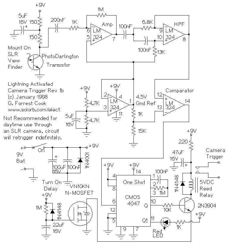
This circuit is used to trigger a camera's electronic shutter circuit when a flash of lightning is present. This circuit would also work for photographing fireworks displays or other events involving flashes of light. More: In a nutshell, the...
This circuit incorporates a datasheet-compliant trigger signal, reversed polarity protection, an optional test button, and the capability for battery operation. It utilizes either the U1 L601E3 or MAC97A8 triac, rated for 400 V and 1 A. When U1 is...
This circuit was designed for digital cameras, which are known to have significant power consumption. For instance, the Minolta E223 camera requires approximately 800 mA. In practice, this demand can be met using a mains power supply or high-capacity...
This project is a fun and safe activity for individuals interested in magnetically launching projectiles. The operation involves placing a ferromagnetic projectile at one end of a coil and applying a power pulse. The key is to turn off...
Speaker relay delay controlling circuit for audio amplifier The speaker relay delay controlling circuit is designed to manage the connection of speakers to an audio amplifier, ensuring that the speakers are activated only after a specified delay. This delay serves...