
Batteries charger & PSU - ideal for digital camerass

The described circuit for digital cameras integrates a charger and an adapter, effectively addressing the power requirements of devices with high consumption rates. The adapter utilizes an LM317 adjustable voltage regulator, which is versatile for various camera models. The output voltage range of 2-9 V is particularly beneficial, allowing compatibility with different camera power specifications.
The charger section employs a 7805 voltage regulator, ensuring a stable output that is essential for safe battery charging. The inclusion of a potentiometer allows for fine-tuning of the charging current, which is critical for battery health and longevity. The ability to charge multiple batteries simultaneously enhances the circuit's utility, making it suitable for users with multiple battery packs.
The mechanical mains timer adds a layer of functionality, allowing users to set charging durations based on manufacturer recommendations. This feature compensates for the lack of automated charging time measurement in the circuit, ensuring that batteries are charged adequately without the risk of overcharging.
Overall, the circuit is designed with practicality in mind, offering a straightforward solution for powering and charging digital cameras while accommodating various battery configurations. The components selected for this design are commonly available, making the circuit accessible for hobbyists and professionals alike.This circuit was created for digital cameras. It`s known the digital cameras have considerable power consumption. For example my camera Minolta E223 requires approximately 800 mA. In practice a mains power supply or high capacity NiMH accumulators (batteries) can satisfy this demand. This circuit consists of two parts, charger and adapter. The tra nsformer, rectifier bridge and buffer condensator are common. Adapter is quite simply its main part is an adjustable voltage regulator LM 317 according to usual setting. Output is a suitable for camera jack plug. Voltage can be adjusted in range 2-9 V. In the charger circuit a 7805 fixed voltage regulator works as current generator assured constant current during charging.
This charging current can be adjusted with the 100 /1W potentiometer in range about 50-300 mA indicated by a small current measuring instrument. From one to four batteries can be charged simultaneously. The switch must be set according to number of batteries, and charging current of batteries given by manufacturer must be adjusted.
This circuit doesn`t measure charging time and charging condition of batteries. Manufacturers give charging time, usually 14-16 h. I solved this problem with a simply, cheap mechanical mains timer. I think its accuracy is sufficient. 🔗 External reference
Related Circuits
This circuit, based on the 555 timer, functions as a voltmeter and an analog-to-digital converter, converting analog input voltage into digital output pulses. The 555 timer is a versatile integrated circuit commonly used for timing, oscillation, and pulse generation applications....
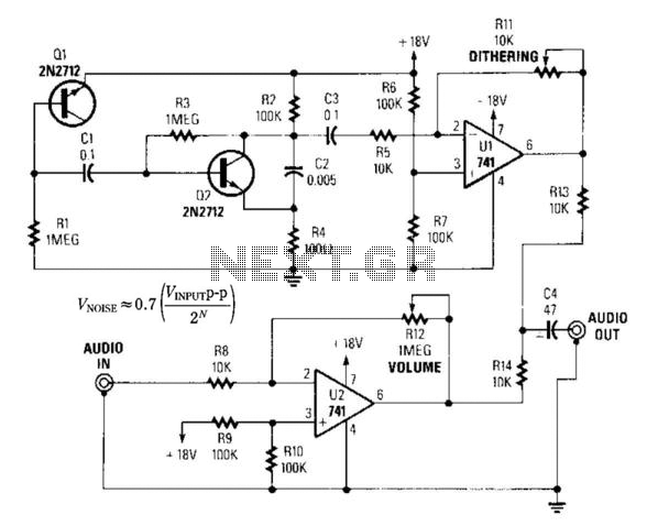
By introducing a small amount of noise to a signal intended for digitization (approximately 0.7 bits), where n represents the number of bits, for instance, an 8-bit signal with a peak-to-peak voltage of 2 V would result in a...
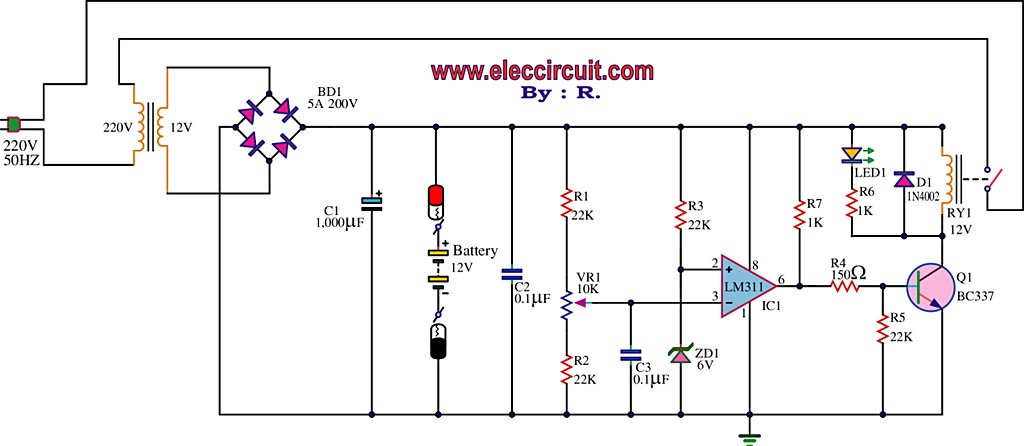
The best 12 Volt battery charger circuit is an automatic system that activates when the battery voltage falls below a specified threshold. This 12 Volt battery charger circuit is designed to efficiently charge lead-acid batteries while ensuring safety and longevity....
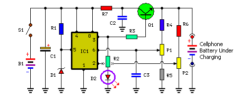
Stops charging when the battery is fully charged. Portable unit for charging mobile phones. Cellphone battery management is a significant issue while traveling, as power supply can be limited. The described circuit functions as an intelligent battery charger designed to...

An FM and AM transmitter integrated into a compact device utilizing the CD4001 integrated circuit. It broadcasts at 20 MHz for AM and 100 MHz for FM. The described transmitter combines both Frequency Modulation (FM) and Amplitude Modulation (AM) capabilities...
The lithium-ion rechargeable battery charger described in the example operates using a constant voltage and current method. It is designed for charging 3.6V lithium-ion batteries commonly found in various mobile phones. The circuit's working principle involves a battery charger...