
Homebuilt RS232 LCD Interface

The described circuit focuses on a robust RS232 interface that operates at TTL levels (+5V) while generating the necessary voltage levels of +/- 10 to 11 volts in accordance with RS232 specifications. This design is particularly advantageous for applications requiring long cable runs, as it maintains signal integrity over extended distances, similar to traditional RS232 implementations.
The circuit typically includes a voltage level shifter or a dedicated RS232 driver IC, which converts the TTL signal levels to the required RS232 voltage levels. This driver IC ensures that the output signals meet the RS232 standard, which is crucial for compatibility with various devices and equipment. The use of such a driver also provides electrical isolation, protecting the connected computer or microcontroller from potential voltage spikes or noise that may occur in automotive environments, such as those found in an "MP3 in car" setup.
Additionally, the design may incorporate capacitors for decoupling and filtering, ensuring stable operation and reducing noise. The circuit can also include protection diodes to safeguard against reverse polarity and over-voltage conditions.
Furthermore, the mention of RS232-LCD controllers indicates that this interface can be utilized for controlling LCD displays via RS232 communication. However, it is noted that many commercially available RS232-LCD controllers may have limitations such as slower response times or lack of button support, which could affect user interaction and overall functionality. This highlights the potential advantages of custom-designed solutions that can address these shortcomings while providing a cost-effective alternative.
In summary, the described RS232 interface circuit is designed to meet the specific requirements of robust communication in various environments, emphasizing reliability, compatibility, and protection for connected devices.There is enough of poorly constructed RS232 alike TTL level interfaces (+5volt) , this one generates it`s own +/- 10..11volts as RS232 specs. require , and is able to use very long cables like RS232 can , and protects computer as well , nice in funny environment like inside a "MP3 in car" setup.
There is plenty of ready RS232-Lcd controllers 4 sale , at least 3 types I know about... Common to them all is that they are slow or does not have button support and/or are expensive... that`s my opinion 🔗 External reference
Related Circuits
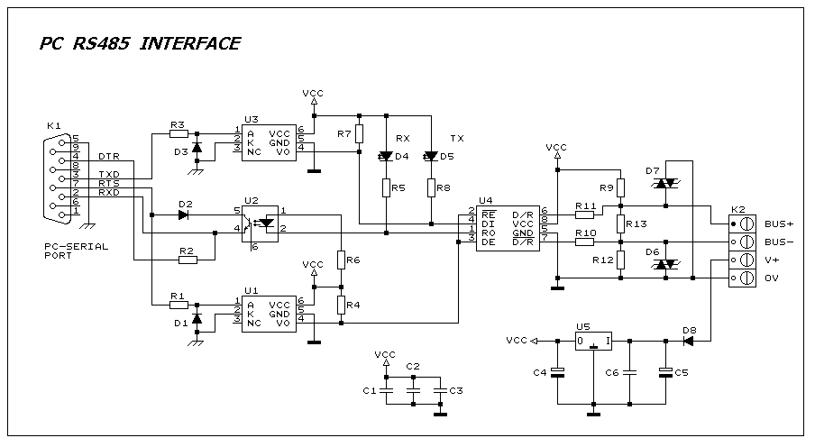
This interface circuit provides electrically isolated RS485 communication interface to the PC serial port. The isolation circuit protects the PC from direct connection to hazardous voltages. More: Figure 1 shows the circuit diagram of RS485 interface. Connector K1 is...
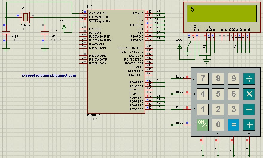
This PIC microcontroller tutorial provides a straightforward method to interface any keypad (e.g., 4x4 or 4x3) with the PIC16F877 microcontroller. This code is written... The tutorial outlines the steps necessary to connect a keypad to the PIC16F877 microcontroller, which is...
The CCFL tube is powered by a small electronic inverter circuit (CCFL inverter) that illuminates the screen electronically. This inverter circuit accepts a low-level DC input voltage and provides a high-level AC output to operate the backlight CCFL tube(s)....
This circuit is utilized in RS-232 serial interface and current loop circuit applications. It converts voltage signals into a 20mA current signal, with a maximum transmission rate of 1200 bits per second. The CCD IC1 and transistor T1 form...
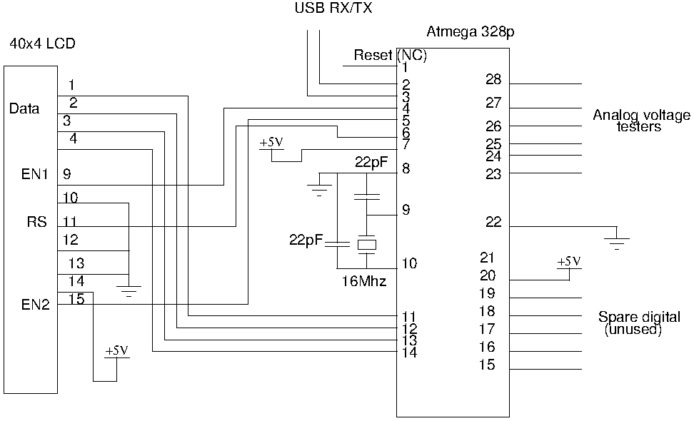
Drive a four-line LCD panel using an Arduino. The project initially aimed to control the LCD for displaying arbitrary information but evolved to include functionalities such as timekeeping, EEPROM read/write operations from the Atmel 328p, and voltage measurement. Multiple...
Unlike most surface-mounted device (SMD) resistors, SMD ceramic capacitors do not have their values marked. To determine the value of these capacitors, a capacitance meter is required. SMD ceramic capacitors are widely used in modern electronic circuits due to their...