
Homemade metal detector circuit

This metal detector circuit operates on the principle of electromagnetic induction, utilizing a coil of wire to generate an oscillating magnetic field. When a conductive or ferromagnetic object enters this field, it induces a change in the magnetic flux, which can be detected by the circuit.
The core components of the circuit include a transmitter coil, which emits the magnetic field, and a receiver coil, which detects the variations caused by nearby metallic objects. A simple oscillator circuit, often based on a 555 timer IC, can be employed to generate the required frequency for the transmitter. The frequency is typically set in the range of a few kHz to ensure effective detection of various metals.
Additional components may include a potentiometer for tuning the sensitivity of the detector, allowing the user to adjust the circuit for different types of metals or ground conditions. A simple audio output device, such as a piezo buzzer, can provide an audible indication when a metal object is detected.
Power supply considerations are also essential; the circuit can be powered by batteries or a DC power source, depending on the design requirements. Proper grounding and shielding techniques should be implemented to minimize interference from environmental noise, which can affect the performance of the detector.
Overall, this homemade metal detector circuit is a practical project for electronics enthusiasts, providing a hands-on experience in understanding basic principles of electromagnetism and circuit design.This homemade metal detector circuit will help you find objects composed of materials with relatively high magnetic permeability. It is not suitable for bu.. 🔗 External reference
Related Circuits
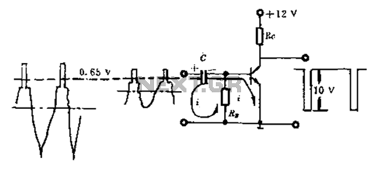
Amplitude separation circuit. A typical amplitude separating circuit is composed of a transistor, capacitance C, and resistances RB and RC. The input signal is a composite video signal, typically with a peak-to-peak voltage of about 2V. The output signal...
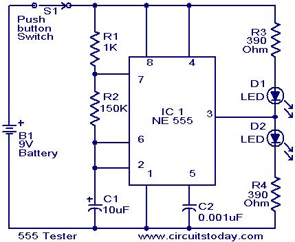
The NE555 timer is configured as an astable multivibrator. When the push button switch S1 is pressed, the LEDs D1 and D2 will flash alternately. When the output is high, D2 will illuminate, and when the output is low,...

This document describes a series of touch switches that utilize only three transistors. These touch-based transistor switches can activate a load simply by the user touching a metal plate. They are designed to directly switch a relay, enabling operation...
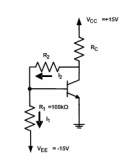
A circuit diagram has been provided for analysis, with the objective of calculating the values of resistors R2 and RC. The circuit is designed to operate at the Q-point with the following parameters: VCE = 5V, VBE = 0.7V,...

The ultrasonic anti-collision circuit is designed using the LM1812 integrated circuit, which controls both the transmission and reception functions. A distance control potentiometer allows for adjustments within a range of 2 to 3 meters. The timebase circuit is constructed...
This circuit was used to stop all the BFO drift. The circuit is extremely stable. Turn the receiver off, and then on at any time and temperature, the BFO frequency is exactly the same. The resonator is a Murata...