
LM1812 uses ultrasonic anti-collision circuit design

The ultrasonic anti-collision circuit operates on the principle of emitting ultrasonic waves and measuring the time taken for the echoes to return after bouncing off an object. The LM1812 circuit serves as the heart of this system, facilitating both the transmission of ultrasonic signals and the reception of their reflections. The circuit includes a potentiometer that allows users to set the desired detection range, typically between 2 to 3 meters, to suit specific applications.
The timebase circuit, which includes a one-shot timer, plays a crucial role in determining when to trigger the alarm. When the distance measurement indicates that an object has entered the preset alarm zone, the input pin of the timebase circuit receives a low signal, which corresponds to about 1/3 of the supply voltage (Vcc). This low signal activates the one-shot timer, causing its output pin to go high. The high output signal is then utilized to illuminate an LED and activate an electronic buzzer, providing both visual and audible alerts.
The T/R-40 series ultrasonic sensor is specifically designed for this type of application, offering reliable performance in detecting objects within the specified range. The circuit can be effectively mounted at the rear of a vehicle to prevent collisions while reversing, ensuring that the driver is alerted to any obstacles in the path. Furthermore, this circuit can be adapted for anti-theft purposes, where it can monitor entry points to a property. If an intruder approaches within the defined range, the system will trigger the alarm, enhancing security for residential, commercial, and financial environments. This versatility makes the ultrasonic anti-collision circuit a valuable tool in various safety and security applications. Circuit principle : ultrasonic anti-collision circuit is shown, when the LM1812 circuit by circuit group to control the transmission and reception of LM1812 (LM1812, ie send an d receive). Available Skfl distance control potentiometer to adjust, and can be controlled 2-3m. Timebase circuit consisting of one-shot circuit, when reaching the alarm distance, time-based circuit pin input low (equivalent to 1/3Vcc) 1, the one-shot circuit is triggered, pin output high. LED lights while electronic buzzer alarm. This circuit ultrasonic transmitting/receiving sensor is T/R-40 series, the circuit can be used for anti-collision car when reversing alarm, installed in the rear of the car can be.
Can also be used for anti-theft alarm, the thief entered the range of 2 ~ 3m, began to alarm for home, warehouse, finance and other departments.
Related Circuits
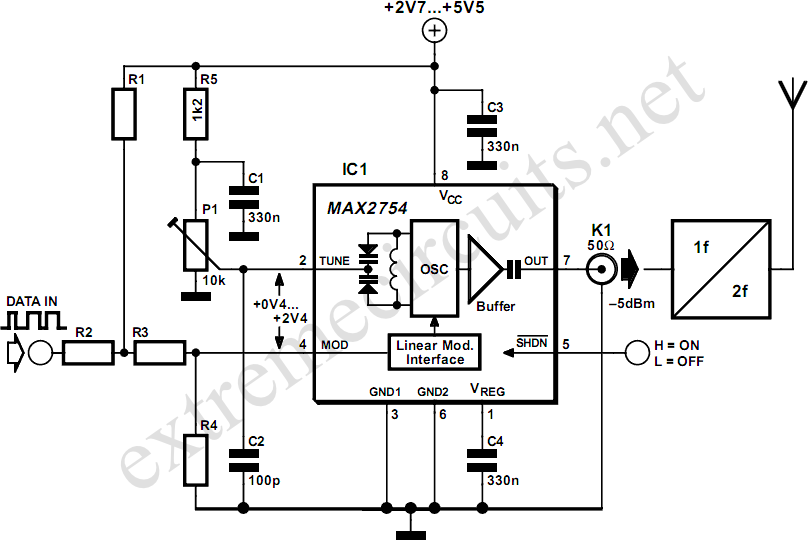
High-frequency voltage-controlled oscillators (VCOs) are challenging to construct, which is why Maxim has developed the integrated 1.2 GHz oscillator, the MAX2754. The center frequency is adjustable via the TUNE input, while a linear modulation input allows for frequency modulation....
The circuit (before flameout) worked like this: device Q1 is a triac, which is a power-switching device. When triggered, it switches to a fully conducting state and stays that way until the current passing through it goes to zero....
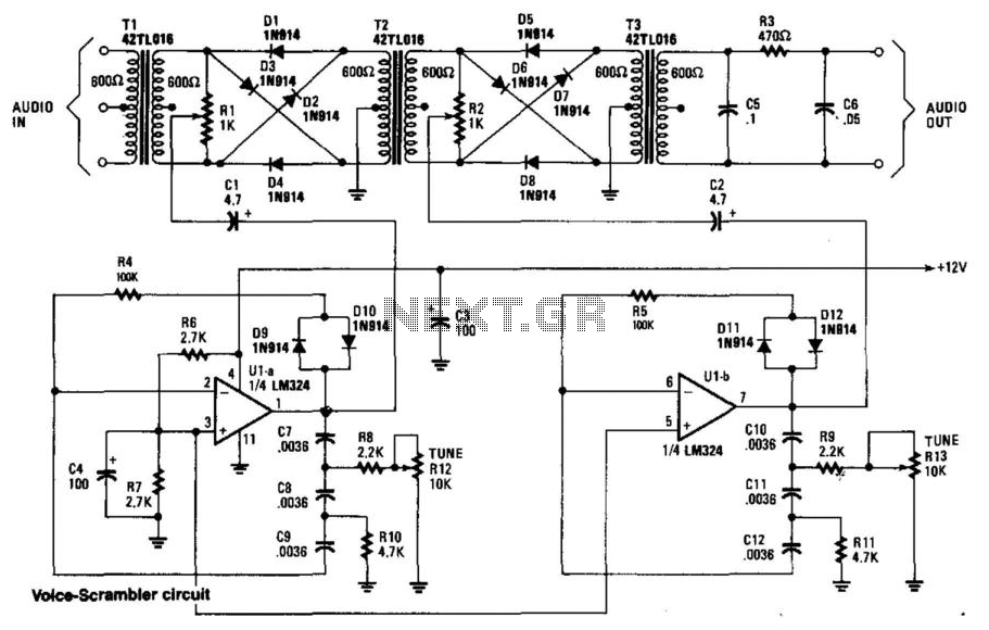
This circuit employs two balanced modulators to generate a Double Sideband (DSB) signal, followed by the reinsertion of a carrier frequency that differs from the original. This alteration leads to distortion of the input signal. While a voice signal...
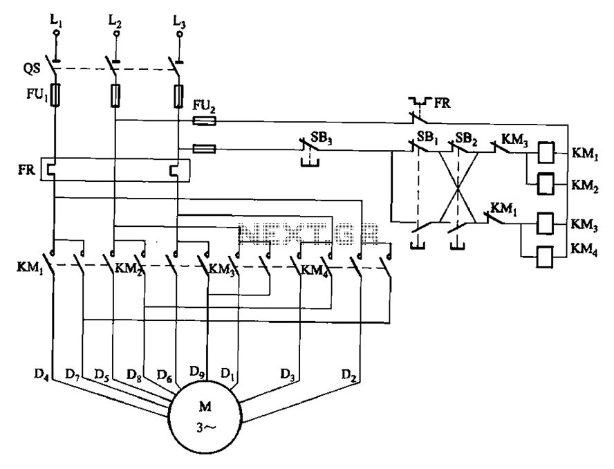
The circuit depicted in Figure 3-112 features two operation buttons: SBi, which serves as the first speed operation button, and SBz, which operates the second speed class. Both buttons facilitate two speeds in the same direction. The circuit design incorporates...
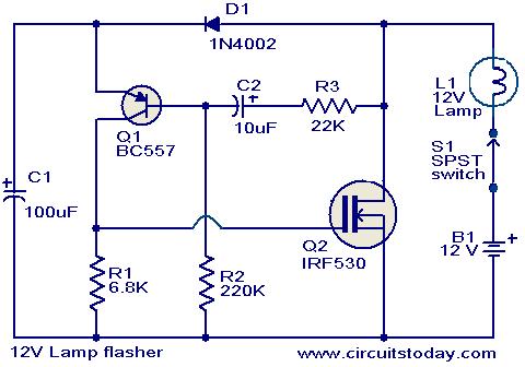
This circuit is a straightforward yet effective solution for flashing 12V lamps, particularly those utilized in automobiles. The flashing mechanism relies on transistor Q1 (BC557) and MOSFET Q2 (IRF530), with Q2 delivering the required drive for the lamp. The...
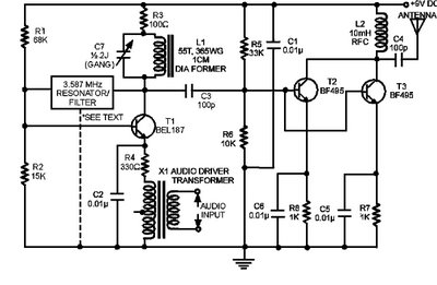
The circuit presented here is a powerful AM transmitter utilizing a ceramic resonator/filter operating at 3.587 MHz. This circuit primarily relies on a transistor for its core functionality. It is possible to use resonators/filters of other frequencies, such as...