
House Alarm Loop Circuit

The alarm circuit operates using a combination of digital logic gates and a transistor to control the siren. The 4001 and 4011 integrated circuits are quad NOR and NAND gates, respectively, which are fundamental in creating the logic required for the alarm's functionality.
The open and closed loop contacts, represented by switches 1, 2, and 3, serve as inputs to the circuit. When a switch is activated, it sends a signal to the logic gates, initiating the alarm sequence. The circuit is designed to maintain the alarm state for a predetermined time (5 to 10 minutes) before automatically resetting. This timing can be adjusted based on the values of external resistors and capacitors connected to the timing circuit within the design.
The triggering delay of 27 seconds allows for a grace period, giving users time to deactivate the alarm before it becomes active. This feature is critical in preventing false alarms during normal entry and exit procedures. The cancel button provides an additional layer of control, enabling users to reset the system quickly if necessary.
The NPN transistor plays a crucial role in driving the siren. When the alarm is triggered, the output from the logic gates activates the transistor, allowing current to flow from the power source to the siren, which produces the audible alert. The choice of an NPN transistor is suitable for this application due to its capability to handle higher current loads, ensuring that the siren operates effectively.
Overall, this alarm circuit is a well-rounded design that incorporates basic electronic components to create a reliable and user-friendly security solution. Adjustments to component values can tailor the performance to specific needs, making it versatile for various applications.This circuit offers open and closed loop contacts (switches 1,2,3) that triggers the alarm ON and stays ON for 5 -10 minutes. The trigering delay (entrance/exit) is 27 seconds. This simple alarm circuit Has also a cancel button for reseting the circuit to stand-by mode again....
It uses 4001 and 4011 gates and one NPN transistor who drives the siren.
Related Circuits
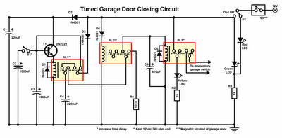
Timer garage door circuit schematic diagram, printed circuit board. The timer garage door circuit is designed to automate the opening and closing of a garage door based on a predetermined time interval. The schematic diagram illustrates the layout and connections...
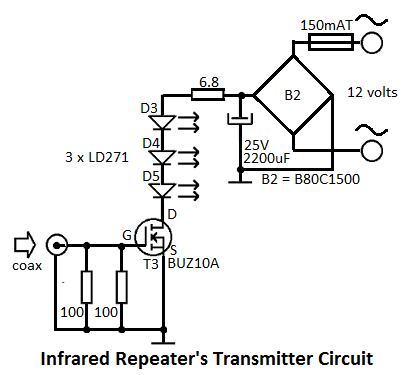
This infrared repeater system is utilized to extend the range of an infrared transmitter used with audio or video equipment up to 10 meters. The original signal is approximately. The infrared repeater system operates by receiving infrared signals from a...
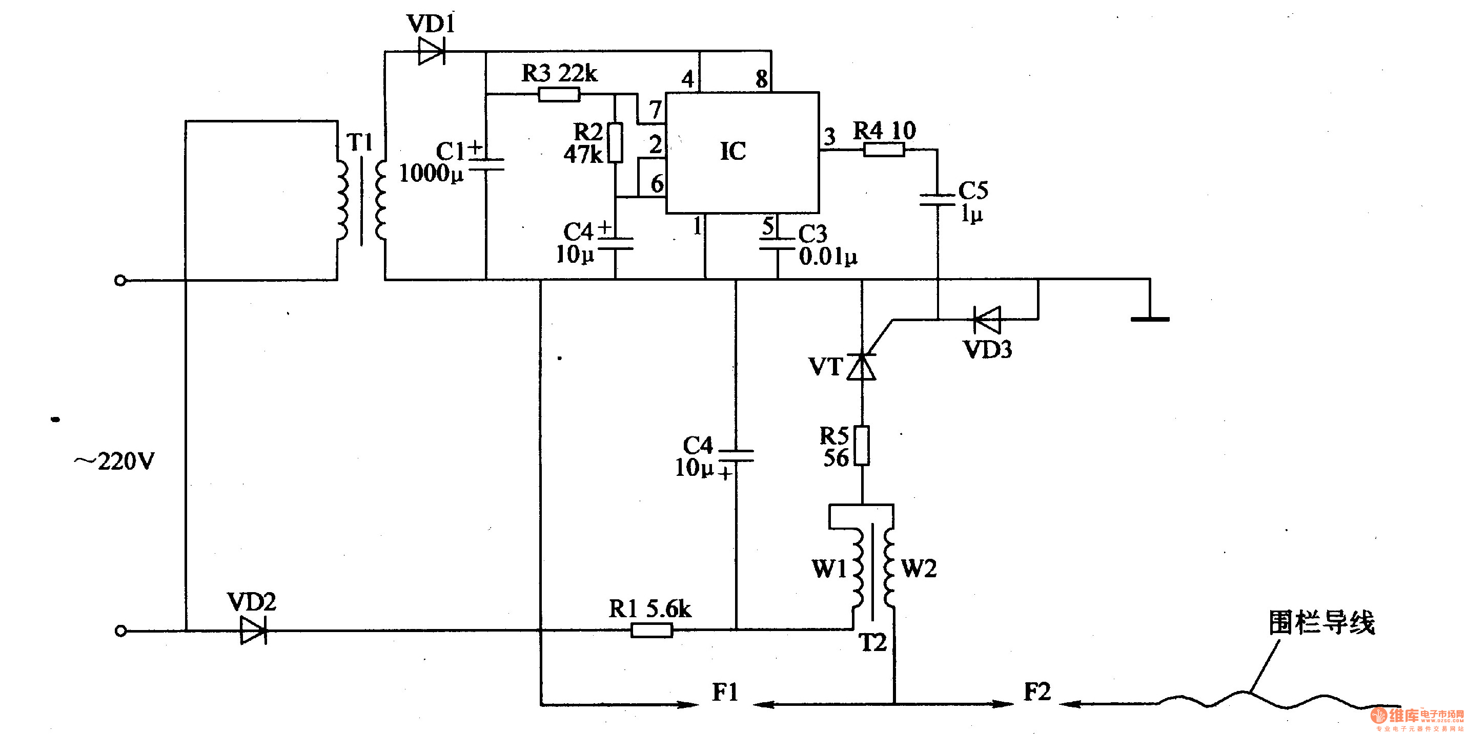
The electric fence control circuit consists of a power supply circuit, a pulse generator, and a high-voltage circuit, as illustrated in Figure 4-27. The power supply circuit includes a power transformer (T1), rectifier diodes (VD1, VD2), filter capacitors (C1,...
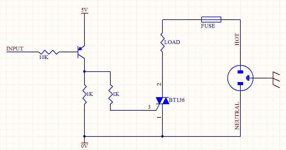
A circuit was designed to function as a light dimmer, utilizing a BT136 SCR and an MOC3022 optocoupler. However, the circuit did not operate as intended. The circuit aims to control the brightness of a light source through phase control...
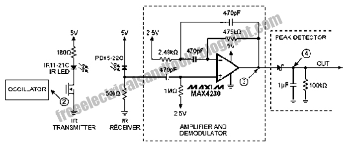
The following circuit illustrates an Infrared Proximity Sensor Circuit Diagram. This circuit is based on the MAX4230 integrated circuit. Features include a 10 kHz oscillator. The Infrared Proximity Sensor Circuit utilizing the MAX4230 integrated circuit is designed to detect the...
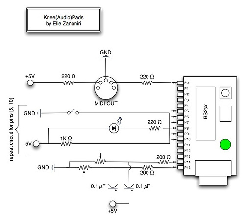
A few nice MIDI controller interfaces were discovered. The Knee(Audio)Pads are a wearable MIDI device. The MIDI controller interfaces mentioned provide innovative solutions for music production and performance. The Knee(Audio)Pads, in particular, represent a unique advancement in wearable MIDI technology....