
Infrared Proximity SensorCircuit Based On The MAX4230 IC

The Infrared Proximity Sensor Circuit utilizing the MAX4230 integrated circuit is designed to detect the presence of nearby objects through the use of infrared light. The core functionality of this circuit is established by the oscillator, which operates at a frequency of 10 kHz, generating a modulated infrared signal.
The MAX4230 is a precision operational amplifier that is utilized in this circuit for its high speed and low noise characteristics, making it suitable for processing the signals received from the infrared emitter and detector. The circuit typically includes an infrared LED that emits light, which reflects off nearby objects and is detected by a photodiode or phototransistor.
The output from the photodiode is fed into the MAX4230, where it is amplified. The amplified signal is then processed to determine if an object is within a specified proximity. A comparator stage may be integrated to compare the amplified signal against a threshold level, resulting in a digital output that indicates the presence or absence of an object.
Additional components, such as resistors and capacitors, are included in the circuit to set the gain of the amplifier, filter out noise, and stabilize the oscillator. The design allows for adjustable sensitivity, enabling the sensor to be fine-tuned for different applications.
This Infrared Proximity Sensor Circuit can be employed in various applications, including object detection in robotics, automated lighting systems, and safety mechanisms in industrial environments. Its compact design and efficient operation make it a versatile choice for proximity sensing tasks.The following circuit shows about Infrared Proximity Sensor Circuit Diagram. This circuit based on the MAX4230 IC. Features: 10kHz oscillator .. 🔗 External reference
Related Circuits
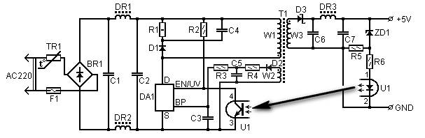
5 Volt/1.5A Switching Power Supply based on the TNY264P power supply. Refer to the designated page for an explanation of the related circuit diagram. The 5 Volt, 1.5A switching power supply utilizing the TNY264P is a compact and efficient power...
This circuit employs an HgCdTe demodulation device that can be cooled to 77K using liquid nitrogen. It utilizes a constant current bias for the demodulation device, which is connected to the input port. The voltage amplification factor is 200,...
The SC41343 is designed as a type of infrared, ultrasonic, or RF remote control launch coding circuit. The internal circuit comprises a sequence generator, control logic circuit, 4-bit shift register, data extraction circuit, and latch circuit. Features include the...
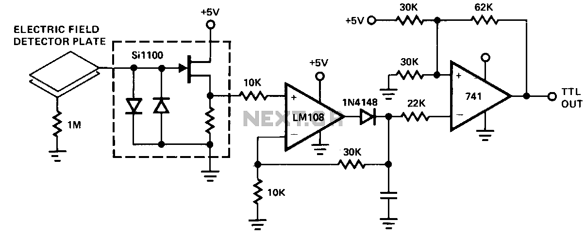
The SillOO series circuit input is connected to a capacitive field sensor, potentially utilizing a double-sided circuit board. Any induced voltage change on the plate is directed to the input of the peak detector section of the operational amplifier...
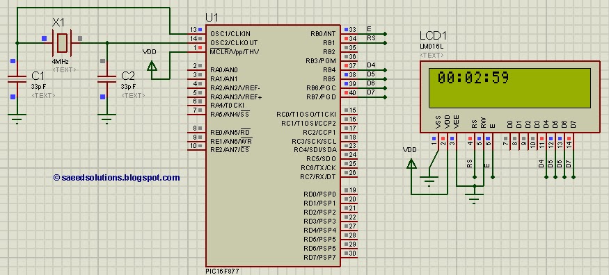
This tutorial on the PIC16F877 microcontroller addresses the question, "How to implement a digital clock using the PIC16F877?" The use of the PIC16 simulator (Proteus) is included. The PIC16F877 microcontroller is a versatile and widely used component in embedded systems,...
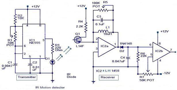
The following circuit illustrates an Infrared Motion Sensor circuit diagram. Features include the use of the NE555 integrated circuit, with a detection zone coverage of 80 degrees. The Infrared Motion Sensor circuit utilizes the NE555 timer IC configured in a...