
How does a Radio Work

The described circuit involves several key components that work together to receive and process radio signals. The aerial, typically a long wire or a rod, captures electromagnetic waves, while the ground connection provides a return path for the signal. The resonant circuit, formed by the coil and capacitor, is crucial for tuning into specific frequencies. The quality factor (Q) of these components directly affects the selectivity and sensitivity of the receiver.
The detector circuit is central to the operation of the Crystal Set. The diode rectifies the incoming RF signal, converting it into a varying DC signal that represents the audio information. The capacitor serves to smooth out the rectified signal, while the load resistor ensures that the circuit can discharge the capacitor at a rate that preserves the integrity of the audio waveform.
The inclusion of a second tuned circuit allows for the reception of frequency modulated signals, expanding the versatility of the receiver. The overall design emphasizes simplicity and efficiency, making it suitable for hobbyists and educational purposes. The historical context of the Crystal Set highlights its significance in the evolution of radio technology, marking a transition from basic wireless communication to more sophisticated broadcasting methods.Thompson and Braun had both discovered or invented the Cathode Ray Tube in 1897 the Amplifying Triode wasn`t invented till 1906 by Lee de Forest. The Diode valve or tube in 1904 by John Fleming. So the era of the "Crystal Set" in the sense of a radio receiver with only Aerial, Earth, Tuned Circuit and passive Detector is really from 1880s till 1906.
Scheduled broadcasts of Speech and Music only started in 1921, when the Crystal Set was already obsolete for 15 years. In reality few people listened to the Wireless on Crystal Sets. They where a hobbyist curiosity by the 1920s. The simplest at low frequencies is a long wire Aerial and connection to metal buried in the ground for an Earth. At high frequencies the cabinet of the radio can be the earth and single rod 1/4 of a wavelength long (8cm approximately for GSM band of 900MHz, it would be 37, 500cm at Long Wave).
This connects to the next section. The simplest kind is a coil "L2" and a capacitor "C1"which forms a parallel resonant circuit. If it used perfect components it would look like a short circuit at every frequency except the desired one and open circuit for the transmission you want. Transmissions are selected by varying the coil or the capacitor, or both. Multiple radio bands are managed by switching in different coils. In a crystal set the coil and capacitor for tuning have to be very low loss, high quality or Q. If the coil is made 15cm (6") to 60cm (24") diameter then no separate aerial and earth is needed on Medium wave.
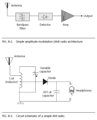
The coil is influenced by the magnetic component of the Electromagnetic waves (Radio Signal). In contrast a long wire on Medium Wave or a "Whip" (rod) aerial on VHF is being influenced by the electric field component of the Electromagnetic waves. The filter connects to the next section The simplest detector only works for A. M. (Amplitude, CW keyed or ASK / OOK [Amplitude Shift Keying/ On Off Keying]). However a second tuned circuit can convert F. M. or FSK (Frequency Shift Keying such as RTTY) into an AM signal. It`s the diode or rectifier as used to convert AC mains to DC. If the amplitude of the AC changes slowly, the resultant DC will vary. You need a capacitor as a low pass filter to remove the AC ripple and a resistor as a load or else the capacitor would charge to the peak of the signal.
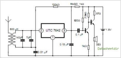
The principle of a Crystal or Diode detector on a Radio tuned circuit is identical. The Frequency is higher 60KHz to 30MHz rather than 50Hz or 60Hz and the variations of the Audio may vary from 20Hz up to 10KHz on AM bands. On Fig. 1 the "load" resistor is the headphones so there is a capacitor "C2" much larger value than the RF tuning capacitor, the quality isn`t so important and the value is large enough to look like nearly a short for the RF (low impedance) but almost open (high impedance) for the 10KHz of Audio.
On Fig 2. the "piezo" earpiece (modern ones are ceramic disc on a metal disc, like a "beeper") is the capacitor (About 2nF to 20nF) and thus only a separate resistor "R1" is needed. The detector feeds the output device. In both cases the diode (crystal detector) charges the capacitor (C2 or ceramic earpiece) from the RF signal and the resistor (R1 or magnetic 2 K Ohm earphones) discharges the capacitor fast enough so the highest modulation frequency isn`t affected too much.
With a larger resistor or capacitor a voltmeter would be a measure of signal strength as the voltage won`t change fast enough to follow the audio signal. This principle is used in more advanced "superhetrodyne" or Superhets to 🔗 External reference
Related Circuits
The fundamental operation of an RF front end is straightforward: it detects and processes radio waves transmitted at a specific known frequency or range of frequencies and modulation format. The modulation carries information of interest, such as voice, audio,...
A low-cost vacuum cleaner system based on the P89LPC901 is introduced in this application note. The design hardware and software are thoroughly discussed. This system can also guide the design of other universal motor driving systems that require robust...
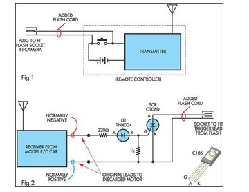
A radio-controlled electronic flash is an essential tool in any photographer's kit. Professionals frequently utilize them, such as wedding photographers. A radio-controlled electronic flash system typically consists of a transmitter and one or more receivers. The transmitter, often mounted on the...
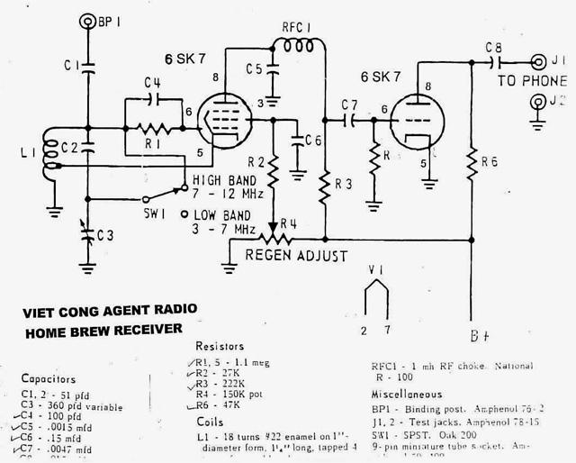
Army Radio Sales Co. specializes in military communications equipment for ham radio operators and collectors. The company offers a variety of military radios from various countries for sale and also engages in the buying and swapping of military radios...
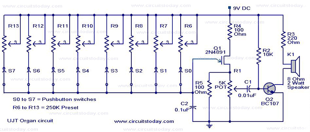
A UJT organ circuit with a circuit diagram is explained in detail. A 2N4891 UJT is used for the operation of the circuit. The UJT (Uni-Junction Transistor) organ circuit is designed to utilize the unique characteristics of the 2N4891 UJT...
The operation is completely safe due to protection against DC and AC short circuits between all pins and ground, thermal over-range conditions, load dump voltage surges up to 40V, and accidental open ground situations. The circuit design incorporates multiple safety...