
Radio Controlled Electronic Flash

A radio-controlled electronic flash system typically consists of a transmitter and one or more receivers. The transmitter, often mounted on the camera, sends a signal to the flash units, which can be positioned away from the camera to create more dynamic lighting effects. This system allows for remote triggering of the flash, enabling photographers to control lighting from various angles and distances.
The transmitter usually operates on a specific frequency, ensuring reliable communication with the receivers. The receivers are connected to the flash units, which can be either built-in or external. Each flash can be adjusted for power output, allowing for precise control over the intensity of the light emitted. Some systems also support multiple channels, enabling the use of multiple flash units simultaneously without interference.
In terms of power supply, these flashes often utilize rechargeable batteries, providing a balance between portability and performance. The design of the flash units typically incorporates a high-capacity capacitor to store energy for quick discharge, allowing for rapid firing rates essential for capturing fast-moving subjects.
Photographers can also benefit from features such as TTL (Through The Lens) metering, which automatically adjusts the flash output based on the camera's exposure settings. This feature simplifies the process of achieving the correct exposure, particularly in dynamic shooting environments.
Overall, a radio-controlled electronic flash enhances the versatility and creativity of lighting techniques in photography, making it an indispensable component for both amateur and professional photographers.A radio controlled electronic flash is a useful item in any photographer s kit. Professionals use them all the time. For example, a wedding photographer w.. 🔗 External reference
Related Circuits
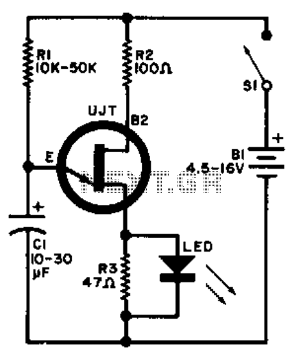
A relaxation oscillator is employed to flash an LED in the base circuit. The capacitor C1 is charged slowly through resistor R1 by the power source, and then it is discharged periodically through resistor R3 and the LED by...
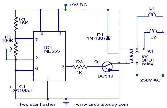
A circuit designed to alternately flash two Christmas stars is presented. The NE555 integrated circuit (IC1) is configured as an astable multivibrator. When IC1 outputs a positive pulse, transistor Q1 becomes conductive, activating relay K1. Consequently, lamp L2, connected...
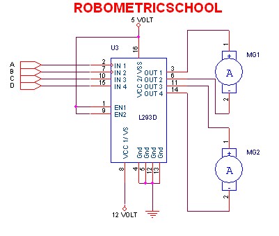
The electronic schematic of a DC motor driver using the L293D, as illustrated in Figure 2, enables the control of two DC motors continuously. It allows for one motor to rotate clockwise while the other rotates counterclockwise. Additionally, all...

The radio is a single-tuned set featuring dual 365 capacitors for tuning on both the antenna and detector sides of a single coil. The coil is designed with multiple taps, a concept that was initially unfamiliar but intriguing. The...

The integrated circuit (IC) is a multistandard vision and sound intermediate frequency (IF) phase-locked loop (PLL) demodulator that operates without the need for alignment. It supports multiple standards, including PAL, SECAM, and NTSC, and is capable of processing both...

The recommendation regarding the existing phono connector is to maintain its current configuration without making significant alterations. The procedure involves replacing the electrolytic and paper capacitors, adding a three-wire line cord, and utilizing the radio in its original state....