
How the capacitor works (in a debouncing circuit)
")
In this circuit, the primary issue revolves around the interaction between the capacitor and the LED. When the switch is closed, the capacitor begins charging. If the capacitor is fully charged, it presents a high impedance path, effectively blocking current flow to the LED, preventing it from lighting up. This behavior is due to the capacitor's ability to store electrical energy; once charged, it does not allow further current to pass through until it discharges.
To clarify how a fully charged capacitor differs from a simple wire, it is essential to note that a wire provides a low-resistance path for current flow, while a capacitor acts as a temporary energy storage device. When the switch is closed, current flows into the capacitor, and once it reaches its maximum voltage (the capacitor's rated voltage), the current flow ceases until the capacitor is discharged.
The mention of a debouncing circuit indicates that the circuit may be intended for use with a mechanical switch, which can produce multiple signals (bounces) when toggled. The design should include appropriate resistors to filter out these bounces and provide a stable signal to the LED. The choice to keep resistors R5 and R6 separate allows for more precise control over the timing and behavior of the circuit, ensuring that each resistor can be tailored to fulfill a specific role, such as controlling the charge and discharge rates of the capacitor.
In summary, the circuit's functionality hinges on understanding the charging and discharging behavior of the capacitor, the role of resistors in stabilizing the circuit, and the need to address mechanical switch bounce to achieve reliable LED operation.Understand how come the LED will not light up as the Capacitor looks like it`s by-passing the switch. When the capacitor is full, it doesn`t transmit/conduct electricity You`ll notice that I`m very beginner, but after 20 hours of reading various tutorials, I still can`t really figure out something very simple; how the full capacito
r act differently than a simple wire Edit: Some people pointed out that the debouncing circuit was making no sense ( bad voltage, etc. ) Here`s my 2nd attemps to make more sense. R5 and R6 could be the same, but I thought keeping them separate would help to keep 1 job to each component.
🔗 External reference
Related Circuits
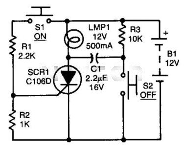
After the SCR is activated, capacitor CI charges up to nearly the full supply voltage through resistor R3 and the anode of the SCR. When switch S2 is later closed, it grounds the positive terminal of CI, causing the...
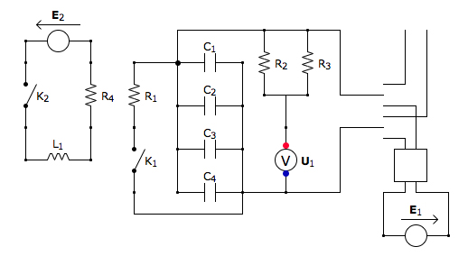
This is the discharging circuit. The red lines indicate the flow of energy from the capacitors to the terminals when the switch is in the upward position. The circuit is complete due to the connection of the terminals by...

An LCD (liquid crystal display) is an electronically modulated optical device composed of multiple pixels filled with liquid crystals, arranged in front of a light source (backlight) or reflector to generate images in either color or monochrome. The block...
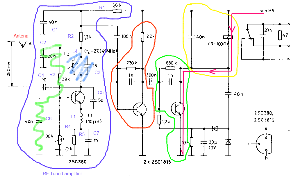
The circuit described is a toy car receiver, which operates similarly to the transmitter but in reverse and with additional filtering. The receiver is tuned to a frequency of 27.145 MHz to capture signals at this frequency. Following the...
The NCP5810D is a dual-output DC/DC converter capable of generating both positive and negative voltages. This device is optimized for powering modules such as AMOLED display drivers, where high output voltage accuracy, regulation, signal integrity, and compact design are...
High voltage electrolytic capacitors in valve equipment can deteriorate if the equipment is unused for an extended period. This deterioration manifests as reduced capacitance and significantly increased leakage current. In some instances, the capacitor may become nearly short-circuited. Using...