
Scr Capacitor Turn-Off Circuit

In this circuit, the silicon-controlled rectifier (SCR) plays a crucial role in controlling the flow of current. Initially, when the SCR is turned on, it allows current to flow through the circuit. The capacitor CI, connected through resistor R3, charges up to the supply voltage, enabling the SCR to remain in its conductive state.
When switch S2 is closed, it creates a path to ground for the positive terminal of CI. This action causes the voltage at the anode of the SCR to drop momentarily below zero, effectively reverse-biasing the SCR. This condition is essential for turning off the SCR, as it disrupts the current flow through the device. The rapid discharge of CI ensures that the SCR remains off for a sufficient duration, preventing any unintended re-triggering.
The choice of a non-polarized capacitor CI is critical in this design, as it allows for bidirectional current flow without the risk of damage due to incorrect polarity. This feature enhances the circuit's reliability and performance, particularly in applications where the voltage polarity may change.
Overall, this configuration demonstrates a practical method for controlling an SCR using a capacitor discharge, providing a reliable means to manage the switching characteristics of the SCR in various electronic applications. After the SCR turns on, CI charges up to almost the full supply voltage via R3 and the anode of the SCR. Whe n S2 is subsequently closed, it clamps the positive end of CI to ground, and the charge on CI forces the anode of the SCR to swing negative momentarily, thereby reverse-biasing the SCR and causing it to turn off. The capacitor"s charge bleeds away rapidly, but it has to hold the SCR"s anode negative for only a few /is to ensure turn-off.
CI must be a nonpolarized type.
Related Circuits
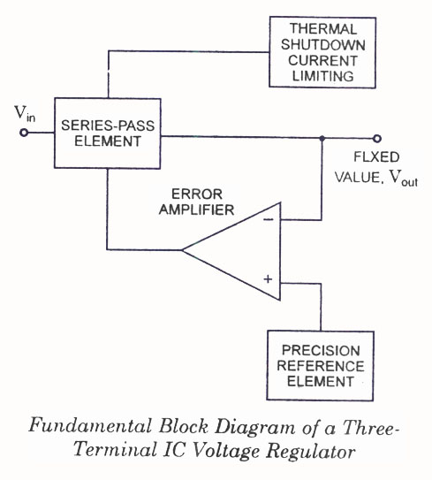
IC Voltage Regulators - Circuit diagram and block diagram of linear, fixed, adjustable (positive and negative), and switching voltage regulators. IC voltage regulators are essential components in electronic circuits, providing stable output voltages from a varying input voltage source. They...
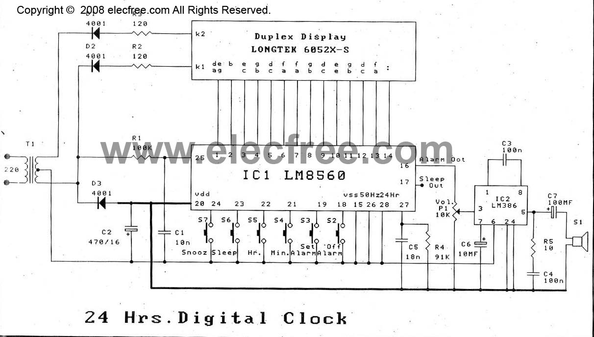
The digital time clock circuit is of great interest to electronic amateurs. The most popular clock ICs include the LM8361 and MM5387. Unfortunately, these ICs... The digital time clock circuit serves as an essential component for various electronic applications, providing...
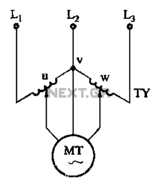
The circuit shown in Figure 3-177 utilizes two single-phase voltage regulators connected to a V-shaped configuration of single-phase regulators. This setup allows for the simultaneous adjustment of voltage and balance, enabling performance akin to a three-phase balanced adjustment. The circuit...
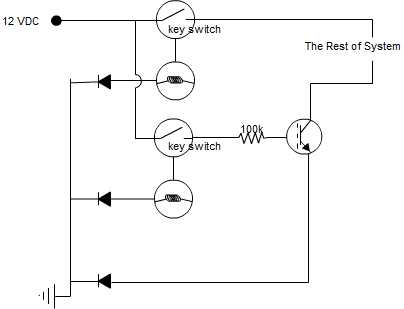
A circuit is being designed that incorporates two key switches, which must both be closed for current to flow through the circuit. The proposed circuit configuration employs two key switches connected in series. In this arrangement, the current can only...
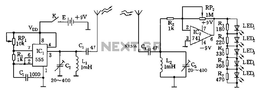
The circuit diagram of the device features a 555 timer IC configured as a transmitter and a receiver, divided into two sections. The 555 timer in the transmitter section serves as the core component of a frequency oscillator. The...
This is a basic lift circuit. When the P1 push button is pressed, the lift starts operating from the 1st floor to the 2nd floor. After a specified time duration, it automatically moves to the 3rd floor. The same...