
how to make digital voltmeter

The digital voltmeter circuit utilizes the ICL7107 integrated circuit, which is specifically designed for digital voltmeter applications. The ICL7107 converts the analog voltage input into a digital output that can be displayed on a 3.5-digit LED display. The LED display is configured to show voltages up to 199.9V, with the capability of indicating negative voltages through its display functionality.
Powering the circuit with a regulated 5V supply ensures stable operation, while the low current consumption of approximately 25mA makes it suitable for battery-operated applications. The compact design of the printed circuit board (PCB) measuring 3cm x 7cm allows for easy integration into various electronic projects or devices.
To enhance the visibility of the LED display, the brightness can be tailored by manipulating the number of 1N4148 diodes in series with the display segments. This flexibility enables users to optimize the display for different lighting conditions. The inclusion of a 220-ohm resistor connected to pin 4 of the LED display is critical for limiting the current and protecting the display from potential damage.
The versatility of the voltmeter is further enhanced by its ability to measure different voltage ranges. By substituting the existing 1M ohm resistor with a 100K ohm resistor, the circuit can accurately measure lower voltages, specifically from 0 to 19.99V, with an impressive resolution of 0.01V. This feature makes the voltmeter suitable for applications requiring precise voltage measurements, such as in laboratory settings or for troubleshooting electronic circuits.This digital voltmeter is ideal to use for measuring the output voltage of your DC power supply. It includes a 3. 5-digit LED display with a negative voltage indicator. It measures DC voltages from 0 to 199. 9V with a resolution of 0. 1V. The voltmeter is based on single ICL7107 chip and may be fitted on a small 3cm x 7cm printed circuit board. The c ircuit should be supplied with a 5V voltage supply and consumes only around 25mA. Brightness of the LED display segments can be varied by adding or removing 1N4148 small signal diodes that are connected in series. Use two 1N4148 diodes for higher LED display brightness. 220 Ohm resistor should be connected to the PIN 4 on the first LED display. The voltmeter can also be configured to measure different voltage ranges and display higher voltage resolution.
Replacing 1M with 100K resistor will allow to measure 0 - 19. 99V voltages with 0. 01V (10mV) accuracy. 🔗 External reference
Related Circuits
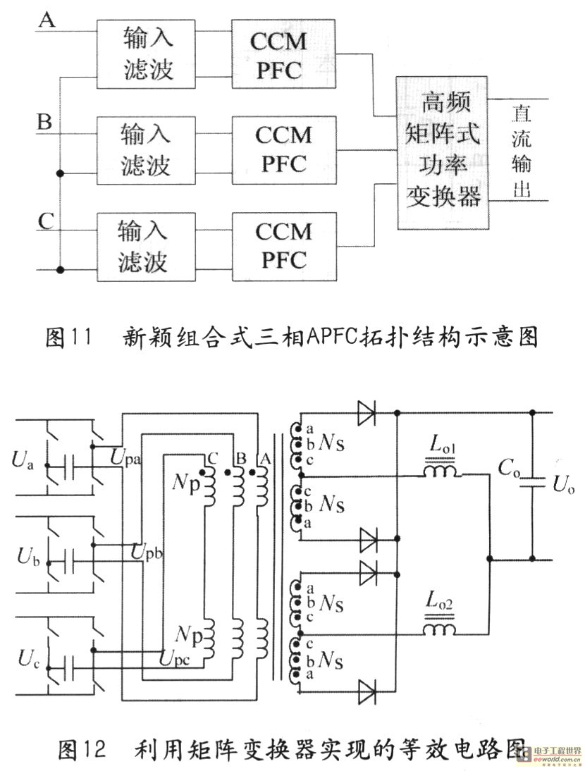
Tape isolate single-phase power factor correction (PFC) that utilizes DC/DC converters, consisting of two cables. The three-phase PFC is formed by connecting three single-phase PFCs in parallel at the output. This configuration is based on a matrix-type DC/DC converter...
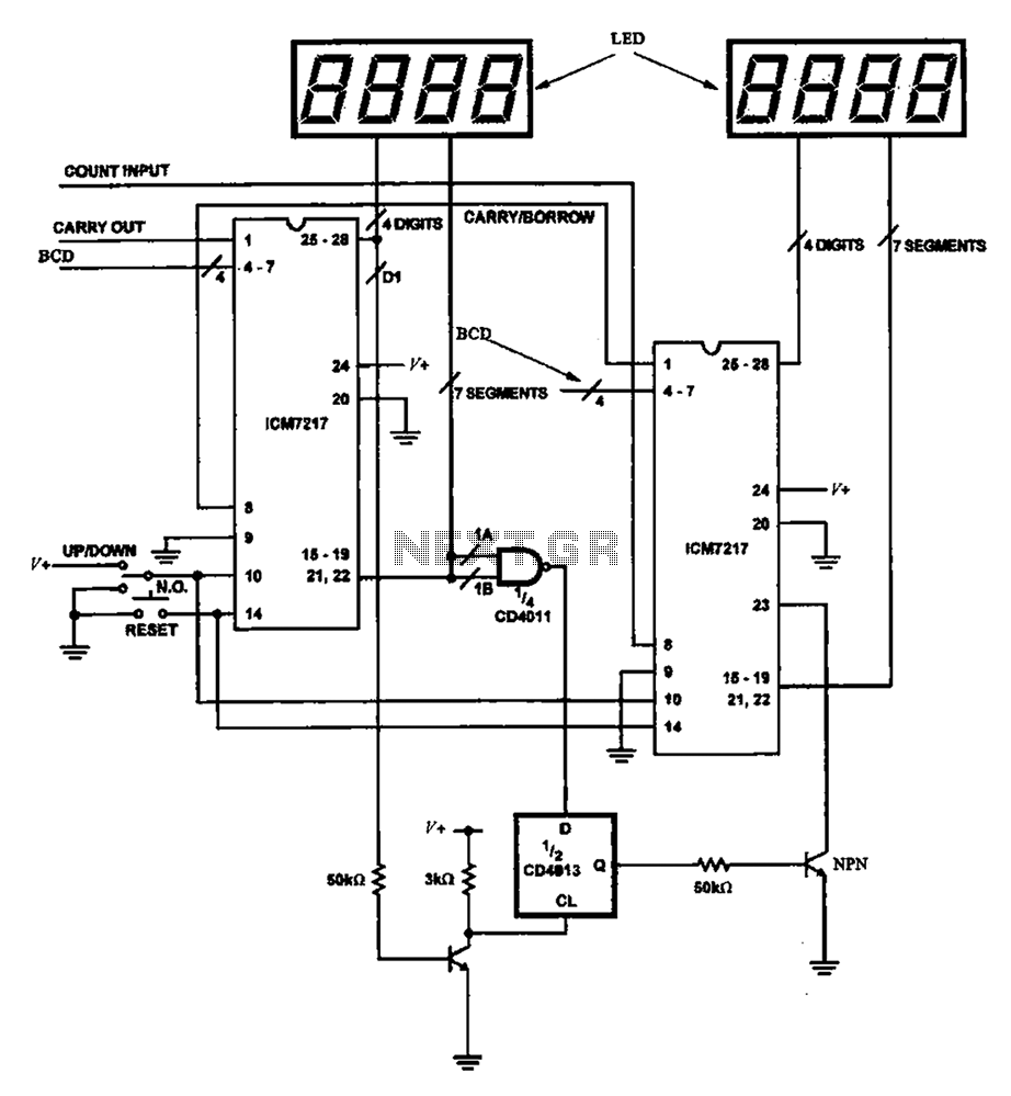
Figure 8 illustrates a potential digital counter circuit. This circuit employs two ICM7217 integrated circuits, with each controlling four digital display tubes. The digital counter circuit primarily utilizes the ICM7217, a highly integrated chip designed for driving seven-segment displays. Each...
The following circuit diagram depicts a variable power supply controlled by a PIC microcontroller. An LCD display is utilized to show the actual output current and voltage values. This digital power supply incorporates a push-button switch to adjust the...
This 4.5-digit digital voltmeter (DVM) circuit is designed around the Maxim ICL7129ACPL analog-to-digital converter (A/D converter) and an LCD driver. It utilizes an ICL8069 CCZR 1.2-V band-gap reference diode for voltage referencing. The switch S2a-b-c allows the selection of...
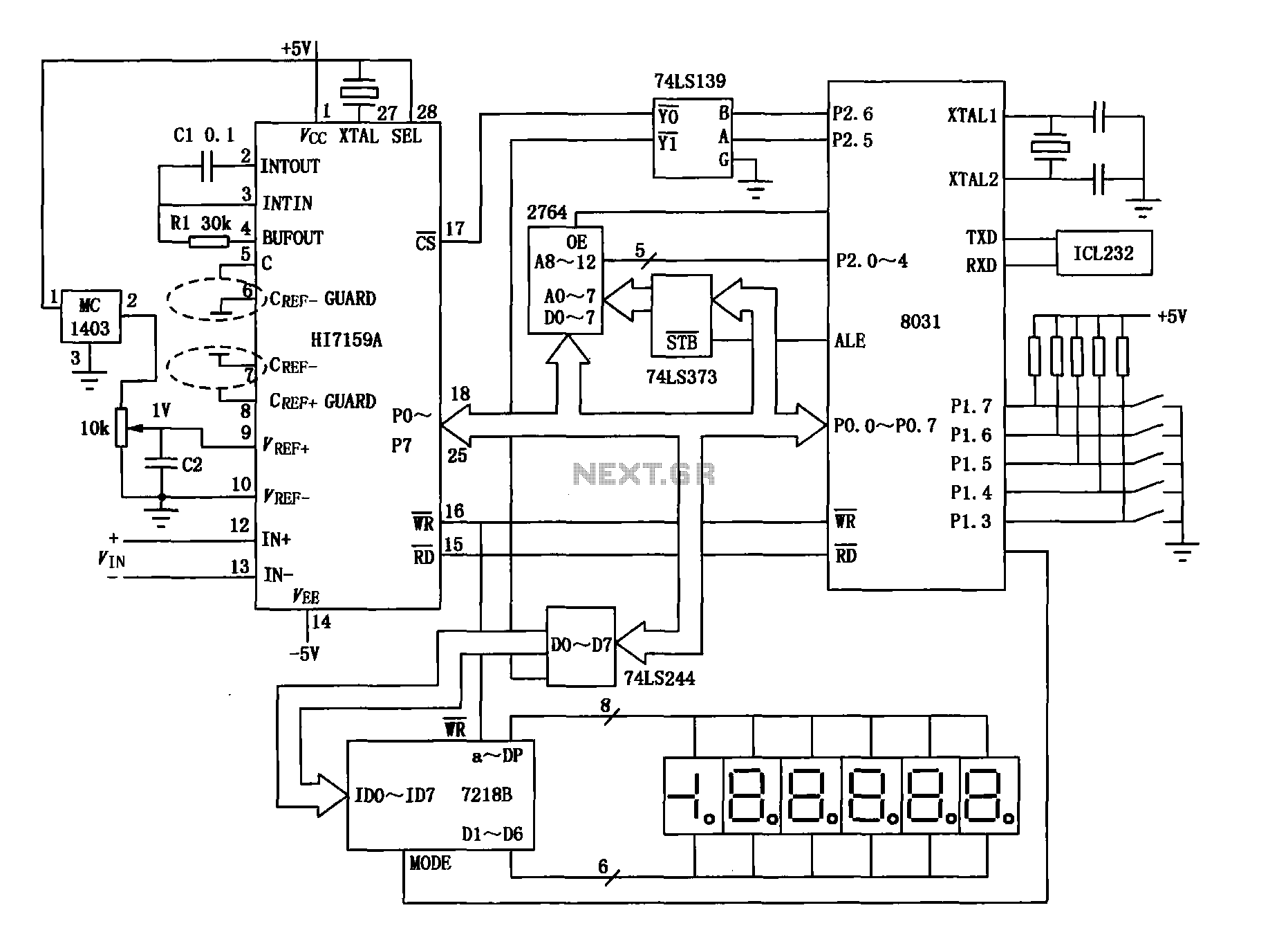
An intelligent digital voltmeter circuit utilizing the HI7159A, 8031 microcontroller, and various other components as illustrated in the figure. The internal circuit incorporates a successive cumulative integrator, digital zero function, low noise BIMOS technology, and other advanced features. In...
The circuit is a comparator that can measure the voltage of a car battery in steps of 1 Volt. The voltage is determined after comparing the voltage of the battery, which is applied to the inverting inputs of amplifiers,...