
8-bit digital counter circuit

The digital counter circuit primarily utilizes the ICM7217, a highly integrated chip designed for driving seven-segment displays. Each ICM7217 can control up to four digits, making it suitable for applications requiring a visual representation of numerical values. The circuit design typically includes a clock input, which dictates the counting speed, and reset functionality to initialize the count.
In this configuration, the two ICM7217 chips are interconnected to expand the counting capability to eight digits. The clock signal can be generated using a simple oscillator circuit, often implemented with a 555 timer or a microcontroller, providing precise timing for the counting operation. The output from each ICM7217 is connected to the respective anodes of the four-digit displays, while the common cathodes are grounded, allowing for the proper illumination of the segments.
Additional components in the circuit may include resistors for current limiting, ensuring that the LED segments do not draw excessive current, which could lead to damage. Capacitors may also be incorporated for debouncing the clock signal to prevent false triggering due to noise.
The overall layout of the circuit should be carefully designed to minimize interference and ensure stable operation. Proper grounding and power supply decoupling are crucial to maintain the performance of the ICM7217 chips, especially in environments with fluctuating power conditions.
This digital counter circuit finds applications in various fields, including digital clocks, scoreboards, and other devices requiring numerical display functionality. Its straightforward design and effectiveness make it a popular choice among electronics enthusiasts and professionals alike.8 shows a possible digital counter circuit. This circuit uses two ICM7217 integrated chips each control four digital tube.
Related Circuits
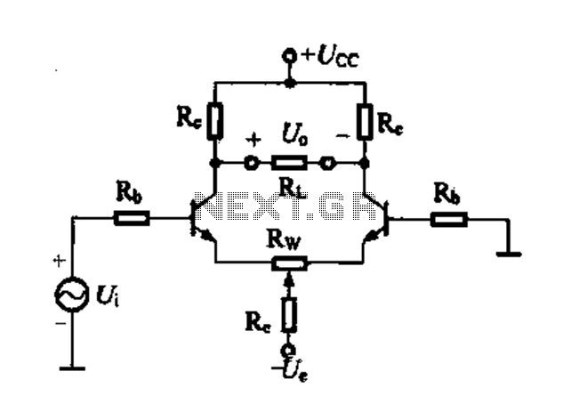
Differential amplifier circuit with four connection methods and characteristics for comparison. The circuit exhibits magnification with a single tube when symmetrical. Additionally, CMRR (Common Mode Rejection Ratio) is adapted from single-ended input to a double-ended output. The differential amplifier is...
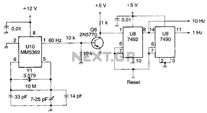
This system utilizes an MM5369 integrated circuit (IC) to generate a 60 Hz signal from a television burst crystal operating at 3.579 MHz. The components F8 and V9 produce 10 Hz and 1 Hz signals derived from the 60...
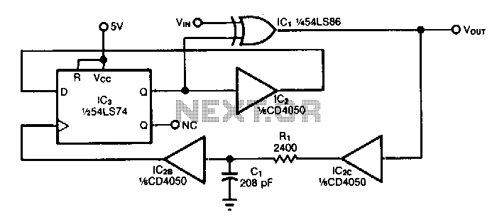
The circuit doubles the frequency of a digital signal by operating on both signal edges. Each transition causes the exclusive-OR gate IC1 to produce a pulse, which clocks flip-flop IC3 after propagating through buffers IC2C and IC2B. If capacitor...
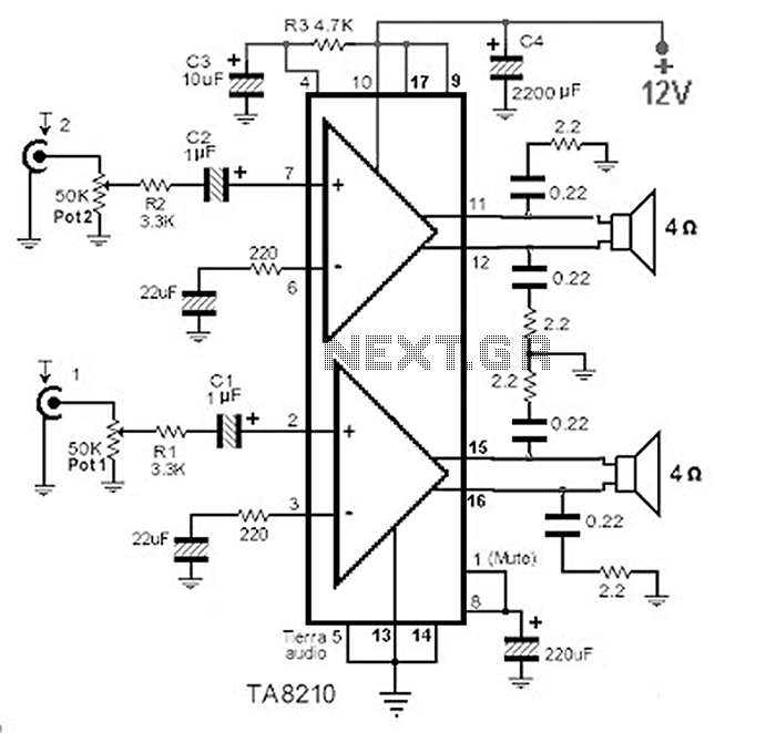
This circuit consists of a 2 x 22 watt BTL amplifier utilizing the IC TA8210AH. It functions not only as an automobile amplifier but is also suitable for low-frequency sound applications, particularly in high-fidelity audio systems, due to its...
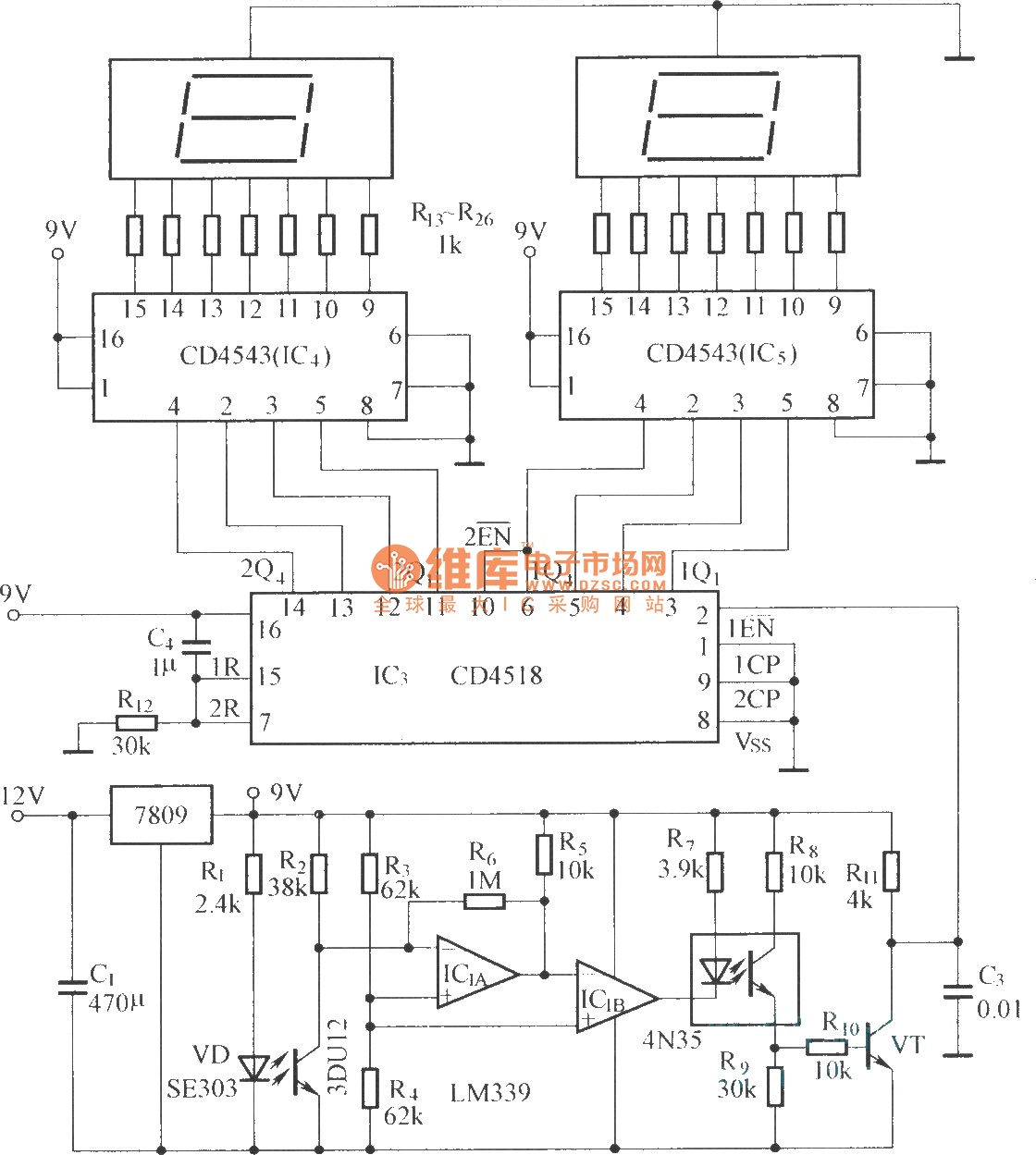
The circuit includes an optical input circuit (VD, 3DU12), a pulse forming circuit (IC1A, IC1B functioning as a voltage comparator; optical coupler; transistor switching circuit), and a counting and display circuit. The circuit architecture consists of several key components that...

The mechanical chassis prototype, as illustrated in the accompanying image, was constructed using two materials: foam and aluminum. Foam was selected for its ease of manipulation, while aluminum was chosen for its excellent strength-to-weight ratio. The prototype features a...