
how to make inexpensive current

The described circuit utilizes the LM317 voltage regulator, a versatile integrated circuit widely used for providing a stable output voltage. In this application, it is configured as a constant current source to safely charge a 12-volt lead-acid battery. The LM317 requires a minimum input-output voltage differential to function correctly, typically around 3 volts. Therefore, the transformer bridge power supply should be selected to provide an adequate input voltage above 15 volts to ensure proper regulation.
Resistor R1 is a fixed resistor that sets a baseline for the output voltage, while variable resistor R2 allows for fine-tuning of the output voltage to match the battery's requirements. The adjustment of R2 directly influences the charging voltage applied to the battery, which is crucial for optimizing the charge cycle and preventing overcharging. The current flowing through the battery is monitored using an ammeter, which provides real-time feedback on the charging status.
The LM317 features built-in current limiting capabilities. When the charging current approaches a predefined threshold, the IC automatically reduces the output voltage to prevent excessive current flow, thereby protecting the battery from potential damage. This feedback mechanism is vital for maintaining battery health and prolonging its operational life.
In summary, this charging circuit is designed to provide a reliable and adjustable method for charging 12-volt lead-acid batteries. By employing the LM317 in conjunction with a transformer bridge power supply, accurate voltage regulation and current limiting can be achieved, ensuring safe and efficient battery charging. The inclusion of an ammeter further enhances the system by allowing users to monitor the charging process effectively.Charging any type of chargeable battery can be critical and involves some attention to be paid. Especially the current or the rate at which the battery is being charged becomes an important factor as far as maintaining life and efficiency of the battery for a longer period of time is concerned. The circuit diagram presented here shows how the IC L M317 ca be configured using just a couple resistors and an ordinary transformer bridge power supply for charging a 12 volt lead acid battery with utmost accuracy. The ADJ pin of the IC is fixed to the junction of the resistor R1 and the variable resistor R2. R2 can be fine set for aligning the final output voltage with the battery. As long as this current is within the desired safe range, the voltage remains at the specified level, however if the current tends to rise, the voltage is withdrawn by the IC and dropped, restricting the current rise any further and ensuring appropriate safety for the battery.
The connected ammeter is used for monitoring the charge condition of the battery. Once theammetershows zero voltage, the battery may bedetachedfrom the charger for the intended use. 🔗 External reference
Related Circuits
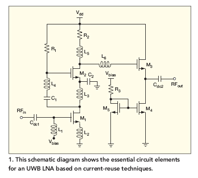
This broadband low-noise CMOS amplifier operates within the ultrawideband (UWB) communications frequency range of 3.1 to 10.6 GHz, utilizing current-reuse techniques. The broadband low-noise CMOS amplifier is designed to enhance signal integrity and minimize noise within the specified UWB frequency...
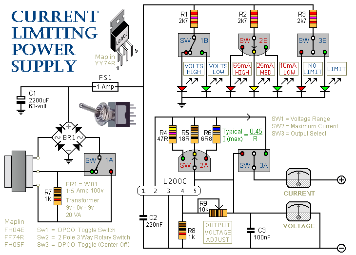
This is a 1-amp variable-voltage power supply unit (PSU) that can adjust the output voltage from approximately 3V to 24V. It includes a feature that allows for the limitation of the maximum output current, which is particularly useful when...
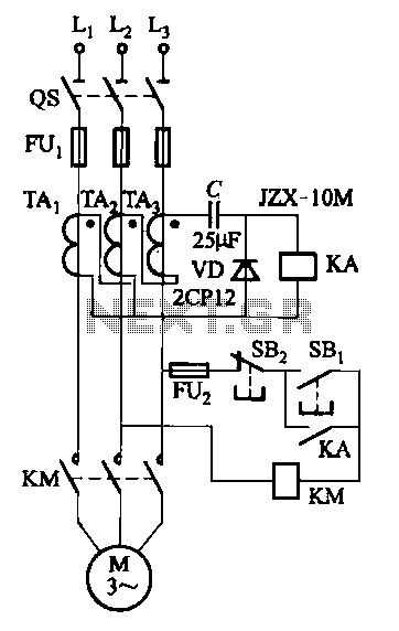
Figure 4-27 (b) line demonstrates a configuration that enhances the output current waveform DC voltage compared to the line in Figure 4-27 (a). This configuration can be utilized for motors with larger capacities. The circuit illustrated in Figure 4-27 (b)...
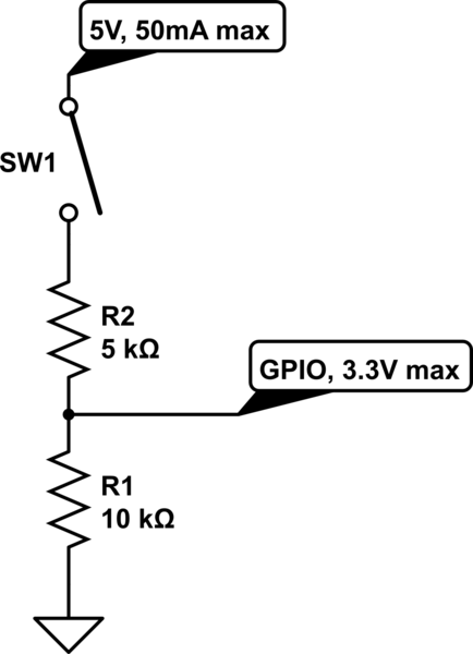
The circuit is designed to limit the maximum voltage between the GPIO input pin and the current source to 3.3V. This is achieved through a voltage divider configuration where the voltage across the 10K resistor is 3.3V, while the...
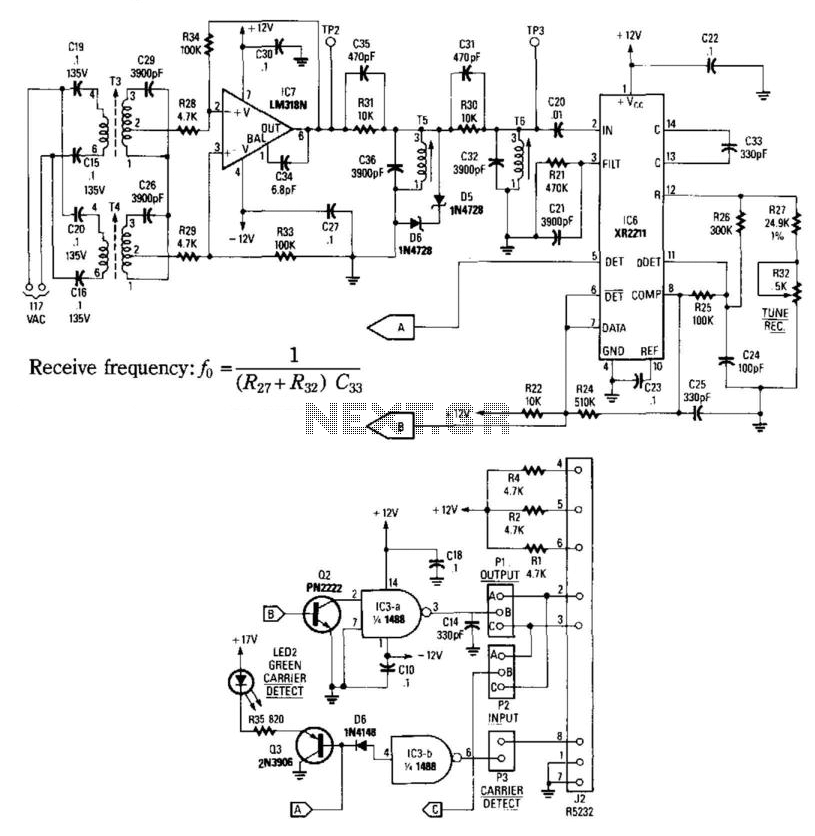
This receiver consists of an input network, amplifier IC7, FSK PLL detector IC8, and output amplifier/interface circuits Q2, Q3, IC3A, and IC3B, which include a 1488 Quad RS232 line driver for the carrier-current signal. The tuned amplifier IC7 amplifies...
This current-limiting circuit, illustrated as part of a small bench power supply, can be utilized with any dual-rail current source. The section of the circuit on the left limits the current entering the dual voltage regulator (IC4 to IC7)...