
how to make simple active low pass

Filter circuits play a crucial role in electronic systems by managing frequency signals for various applications, such as audio processing, radio communications, and signal conditioning. The design of these filters can significantly influence the performance of the overall system. High-pass filters are particularly useful in applications where it is essential to eliminate low-frequency noise or interference, allowing only higher frequency signals, such as audio or data signals, to be transmitted. Conversely, band-pass filters are employed in scenarios where only a specific frequency range is of interest, such as in radio receivers that need to isolate a particular station's frequency while rejecting others.
Passive filters, despite their bulkiness and complexity, are favored in certain applications where power consumption is a critical factor, such as in battery-operated devices. They utilize passive components like resistors, capacitors, and inductors to achieve filtering without the need for external power sources. However, the trade-off is often a less precise filtering capability and larger physical size.
Active filters, on the other hand, utilize operational amplifiers alongside passive components to achieve higher performance levels. They can provide gain, which allows for better signal integrity and can be tuned for specific applications with greater flexibility. The ability to design these filters with discrete components tailored for specific cutoff frequencies, such as 50 Hz, makes them suitable for a wide range of applications, from audio electronics to communications systems.
In summary, the choice between passive and active filters depends on the specific requirements of the application, including factors such as size, power consumption, and performance characteristics. The understanding of frequency behavior and the design of these filter circuits is essential for optimizing electronic systems across various fields.In electronics, filter circuits are basically employed for restricting the passage of a certain frequency range while allowing some other band offrequencyinto the further stages of the circuit. A high pass filter circuit will allow only the frequencies which are higher than thepreferredset range of frequency while a band pass filter will allow only anintermediateband of frequencies to flow to the
next stage, inhibiting all frequencieswhichmay be outside this set range of oscillations. Passive type filter are less efficient and involve complicated inductor and capacitor networks, making the unit bulky andundesirable. However these willnot requireany power requirement for itself to operate, a benefit too small to be considered really useful.
Contrary to this active type of filters are very efficient, can be optimized to the point and are less complicated in terms ofcomponentcount and calculations. The resistors and the capacitors are discretely dimensioned for a 50 Hz cut OFF, meaning no frequency above 50 Hz will be allowed to pass through the circuit into the output.
🔗 External reference
Related Circuits
In pulse position modulation, the amplitude and width of the pulses are kept constant, while the position of each pulse with reference to the position of the reference pulse is changed according to the instantaneous sampled value of the...
The circuit is a standard RC phase shift oscillator that utilizes a single bipolar transistor as the active component. When power is supplied, regenerative feedback is applied through capacitor C2 from the collector to the base of the transistor....
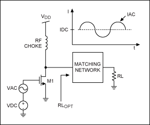
This application note provides a concise overview of power amplifier theory and presents simulation results that offer insights into the operation of the power amplifier across all of MAXIM's LFRF transmitters and transceivers. Power amplifiers are critical components in communication...
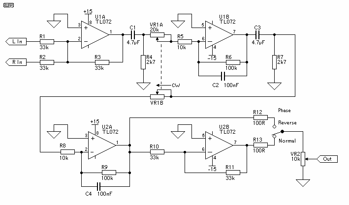
The controller is quite simple. An input buffer ensures that the input impedance of the source does not affect the integrator performance and allows summing of left and right channels without any crosstalk. The output provides a phase reversal...
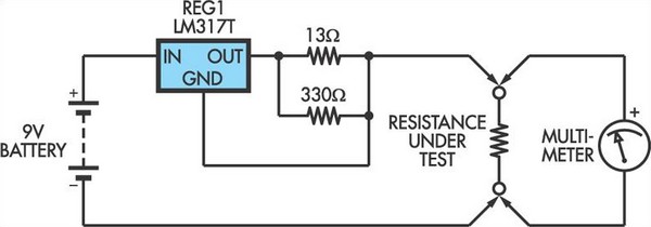
This adapter circuit functions as a 100mA constant current source. It is connected across a low-value resistor, the resistance of which is to be measured, and the resulting voltage drop can then be assessed using a digital multimeter (DMM)....
Application of the High Power LED Driver SP7652 with an Analog 0V-to-10V dimmer. Electrical Requirements: Input Voltage of 5.5V to 28V, Output Voltage VF of LED, Output Current ranging from 0 to 6A. This circuit is designed to provide...