
how to test servo servo tester simple

The servo tester circuit utilizes the 555 timer IC in astable mode to generate a pulse-width modulation (PWM) signal, which is essential for controlling the position of the servo motor. The basic configuration includes a 555 timer, resistors, capacitors, and a power supply, typically ranging from 5V to 12V, depending on the specifications of the servo being tested.
The 555 timer is configured to produce a square wave output that varies in duty cycle, allowing the user to adjust the pulse width. This adjustment is achieved by modifying the resistance values of the connected potentiometer and resistors, which in turn changes the timing of the output signal. The output from the 555 timer is connected to the control wire of the servo, while the power and ground terminals are connected to the respective power supply.
For the construction, a standard 555 timer IC (such as the NE555) is used, along with two resistors and a capacitor to set the frequency and duty cycle of the output signal. A potentiometer can be included to allow for easy adjustments. The circuit is designed to be compact and can be assembled on a breadboard or a printed circuit board (PCB) for more permanent applications.
This servo tester circuit is not only effective for testing standard servos but can also be adapted for use with low-current brushless electric motors. By connecting the motor in place of the servo, the same PWM signal can be used to control the motor's speed and direction, making this circuit versatile for various applications in robotics and model control systems.If you have a servo and you wan`t to test it and you do not have a remote control to do that, or want a tester to test it you can try making the following schematic of servo tester. You can se is based on a 555 timer. The circuit is very simple and cheap to make and it will work just fine. I will post other schematics of servo testers. You can al so use this circuit to test low current brushless electric motors. 🔗 External reference
Related Circuits
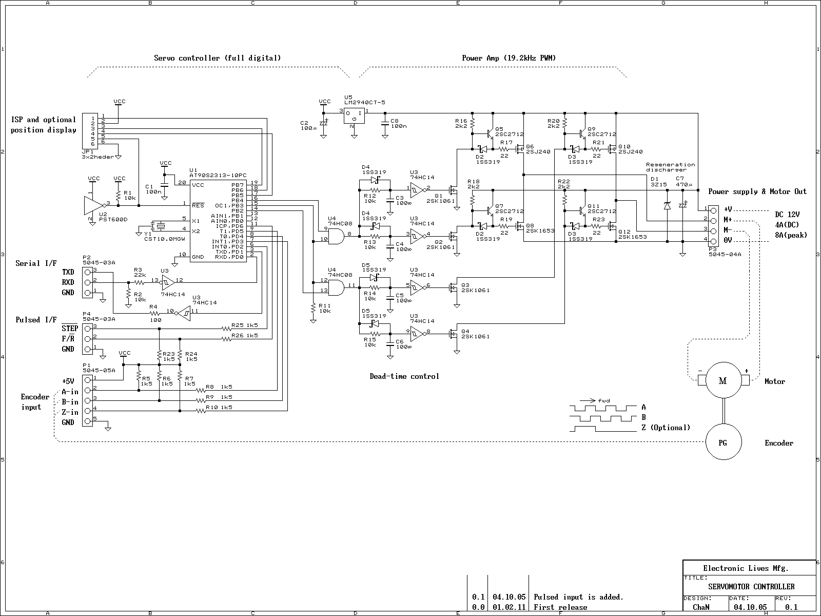
This is an experiment on the closed loop DC servomotor control system (SMC). It will be able to be used for practical use with/without some modifications. The closed loop servo mechanism requires real-time servo operations, such as position control,...
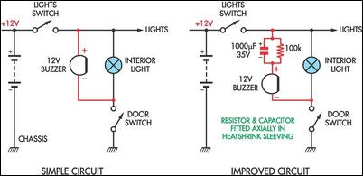
Two headlight reminder circuits are designed for easy installation and operation based on the KISS (Keep It Simple Stupid) principle. The basic circuit consists of a 12V piezo buzzer connected between the lights circuit and a door switch. The...

This document outlines the construction of a simple joule thief circuit. A joule thief is a versatile device, particularly useful for powering LED lights from low-voltage power supplies. It is capable of extracting energy from nearly depleted batteries, making...
An electrician and businessman named Ton Kuiper has invented a circuit that is claimed to produce longitudinal waves, along with many effects similar to those of Nikola Tesla's technology, while being powered solely by a few nine-volt batteries. A...
Using a single 555 Timer IC and a small transformer to generate a high voltage, this circuit will test zener diodes of voltage ratings up to 50VDC. The 555 timer is used in the astable mode, the output at...

The RF Tester (A3014) is a combination of four circuits designed to test various circuit concepts by implementing them and providing enhanced support circuits for their development. The Modulating Transmitter (A3014MT) replaces the previous Modulating Transmitter (A3001A) and allows...