
Simple Headlight Reminders circuit

The two headlight reminder circuits illustrate a straightforward approach to preventing battery drain by providing an auditory alert when vehicle lights are inadvertently left on. The initial circuit design utilizes a 12V piezo buzzer, which is a compact and efficient sound-producing device. This buzzer is wired in such a way that it becomes active when the door switch is engaged. The simplicity of this system makes it accessible for installation in various vehicles, requiring minimal components and tools.
In the improved circuit, the addition of a 1000µF capacitor plays a crucial role in controlling the buzzer's operation. When the door is opened, the capacitor begins to charge, allowing the buzzer to emit a short sound rather than a continuous tone. This design modification significantly enhances user experience by reducing annoyance while still providing an effective reminder. The 100kΩ resistor is strategically placed in parallel with the buzzer to ensure that the capacitor discharges when the lights are turned off, resetting the system for future use.
Overall, these circuits exemplify practical engineering solutions to common automotive issues, balancing simplicity with functionality. The incorporation of basic electronic components, such as a piezo buzzer, capacitor, and resistor, demonstrates how effective designs can be achieved without complex circuitry, making them suitable for a wide range of applications in automotive electronics.These two headlight reminder circuits are easy to install and operate on the KISS (Keep It Simple Stupid) principle. The simple circuit involves adding just a 12V piezo buzzer between the lights circuit and a door switch.
The buzzer sounds if the lights are left on and you open a door. The disadvantage of this simple circuit is that it`s annoying to have the buzzer sound continuously if you want to leave the door open while the lights are on. The improved circuit overcomes that problem by adding a 1000µF capacitor and a parallel 100kO resistor in series with the buzzer.
Now, when a door is opened, the buzzer gives a brief burst of sound only, while the 1000µF capacitor charges. The 100kO resistor discharges the capacitor when the lights are switched off.. 🔗 External reference
Related Circuits

The circuit utilizes the LM129 voltage regulator to produce a 6.9V voltage reference, supplying a current of 1.0147mA from the 6.9V reference voltage to the bridge. The bridge may consist of varistor-type pressure sensors. The LM129 voltage regulator is a...
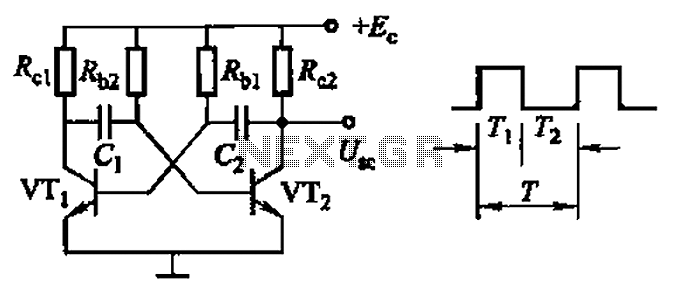
Common non-sinusoidal oscillator circuit, waveform and frequency formula - square wave oscillator - self-excited multivibrator The common non-sinusoidal oscillator circuit, specifically the square wave oscillator, is a fundamental electronic circuit utilized to generate square wave signals. It operates based on...

The circuit functions as a precision bright light control circuit, operating independently of power supply voltage and ambient temperature. Resistors R1, R2, R6, and the photosensitive resistor R5 form a two-arm Wheatstone bridge. The precision bright light control circuit utilizes...

Portable 230V lamp flasher circuit diagram. The circuit is entirely transistorized and powered by a battery. A free-running oscillator circuit is implemented using two low-power, low-noise transistors, T1 and T2. One of these transistors remains in a conducting state...

The following circuit illustrates a Bluetooth-based smart home circuit diagram. This circuit is based on the ULN2003 integrated circuit (IC). Features include an LCD and LED. The Bluetooth-based smart home circuit utilizes the ULN2003 IC, which is a high-voltage, high-current...

This is a single-chip sound level meter that can be used to display the sound level of an amplifier or simply the sound level from a microphone. The core component of the circuit is the IC LM3915 Audio Level...