
Humidty Sensor To Data Aquisition System Interface

U2A, which is part of the LTC1043 switched capacitor building block, provides excitation for the sensor by alternating between 5V and -5V at a frequency of approximately 2.2kHz. This frequency is adjustable, but it is advisable to keep it below 2.4kHz, as this is half the auto-zero rate of U3.
The circuit employs zero-drift operational amplifiers, which are essential for applications requiring high precision and stability. The LTC1250 and LTC1050 amplifiers are designed to minimize offset voltage and drift, ensuring that the output remains stable over time and temperature variations. This is particularly advantageous in low-level signal applications where even minor fluctuations can lead to significant errors.
The LTC1043 serves as a switched capacitor block, which is a critical component for achieving the desired signal conditioning. It is capable of performing various functions, such as filtering and amplification, while maintaining high accuracy. The switched capacitor technique allows for precise control over the gain and bandwidth of the circuit, making it suitable for a wide range of applications.
The design's reliance on a single 5V power supply simplifies the power management requirements, reducing complexity and potential points of failure. The LTC1046's role in generating the negative voltage (-5V) is crucial for powering the operational amplifiers, as many precision amplifiers require dual supply voltages to operate effectively.
U2A's function in providing excitation to the sensor is vital for ensuring accurate readings. The switching between 5V and -5V at a frequency of 2.2kHz allows for dynamic signal processing, which can enhance the performance of the sensor system. The recommendation to keep the switching frequency below 2.4kHz is important for maintaining the integrity of the auto-zero function in U3, which is responsible for eliminating offset errors in the measurement system.
Overall, this circuit design exemplifies a careful balance between cost, performance, and accuracy, making it suitable for applications that demand high precision in low-voltage environments.The circuit shown in the schematic features zero drift operational amplifiers (LTC1250 and LTC1050) and a precision instrumentation switched capacitor block (LTC1043). This design will maintain excellent DC accuracy down to microvolt levels. This method was chosen over the use of a true RMS-to-DC or log converter because of the expense and temperature sensitivity of these parts.
Only a single 5V power supply is required. Integrated circuit U1, an LTC1046, converts the 5V supply to – 5V to supply power to U2, U3 and U4. U2A, part of an LTC1043 switched capacitor building block, provides the excitation for the sensor, switching between 5V and – 5V at a rate of approximately 2.2kHz. This rate can be varied, but we recommended that it be kept below approximately 2.4kHz, which is one-half the auto zero rate of U3.
🔗 External reference
Related Circuits
The circuit operates but exhibits instability, particularly with temperature variations. For example, upon powering it on and tuning it, switching it off and on again affects its performance. The control voltage (CV) output is essential for the theremin/controller circuit....
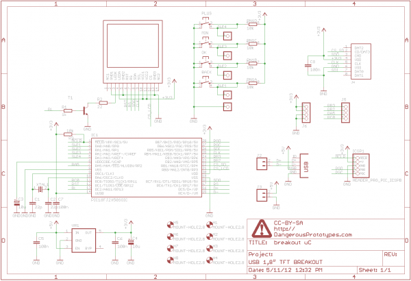
A 1.8" TFT display was sourced from China, and a breakout board was designed for it. This version not only breaks out the pins but also includes a USB-enabled microcontroller and several buttons for graphical user interface (GUI) projects....
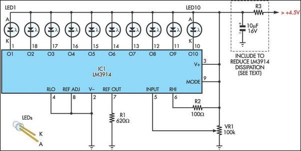
Using LM134 and LM10 integrated circuits, a thermometer can be constructed with a sensing range of -55 to 150 °C. The ideal meter for this circuit is a 0-200 µA. The proposed thermometer circuit utilizes the LM134, a current source...
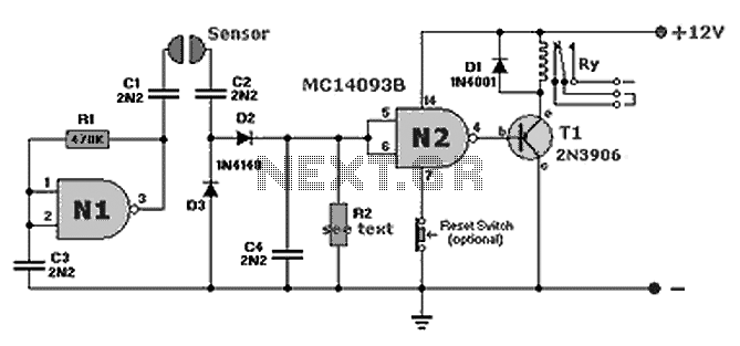
A compact fluid (water) sensor circuit that activates a relay for various applications. Additionally, a printed circuit board (PCB) is not necessary due to the small size of the circuit. The fluid sensor circuit is designed to detect the presence...
Version V2.9 supports a GPS receiver with an ANTARIS chipset while simultaneously utilizing the internal temperature sensor of the MS5534A and the external DS1820 sensor. This version is compatible with 24C256, 24C512, or 24C1024 EEPROMs and includes an internal...
Below is a block diagram of modern automated systems that incorporate closed-loop feedback for motion control. They typically include a servo system that consists of various components. Automated systems utilizing closed-loop feedback mechanisms are designed to enhance precision and responsiveness...