
Fluid Sensor Limiter with MC14093B
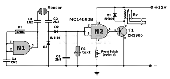
The fluid sensor circuit is designed to detect the presence of water and control a relay based on the sensor's output. This configuration is particularly useful in applications such as automatic irrigation systems, leak detection, and other scenarios where monitoring the presence of water is critical.
The core components of the circuit include a water sensor, a relay module, and a power supply. The water sensor typically consists of two conductive probes that detect the presence of water by measuring the conductivity between them. When water bridges the gap between the probes, the sensor outputs a signal that triggers the relay.
The relay serves as an electromechanical switch, allowing the circuit to control higher voltage devices, such as pumps or alarms, without exposing the low-voltage sensor directly to high currents. The relay coil is energized when the sensor detects water, closing the switch and activating the connected load.
Given the circuit's compact nature, it can be assembled on a small perfboard or directly soldered onto a minimal footprint, eliminating the need for a full PCB. This approach not only reduces material costs but also simplifies the assembly process, making it accessible for hobbyists and engineers alike.
For optimal performance, it is essential to ensure proper power supply ratings and to select a relay that can handle the load requirements of the application. Additionally, incorporating protective elements such as diodes across the relay coil can prevent back EMF from damaging the sensor or other components.
In summary, this fluid sensor circuit is an efficient solution for water detection and control, providing versatility in various applications while maintaining a compact and cost-effective design.A nice and small Fluid (water) sensor circuit that drives a relay for every use that comes to your head :) You do not need pcb because the circuit is to small. 🔗 External reference
Related Circuits

This circuit is a motion detection sensor that utilizes a light source and a detector in the form of an infrared motion detector. The motion sensor employs an infrared LED and a phototransistor. The sensitivity of the sensor can...
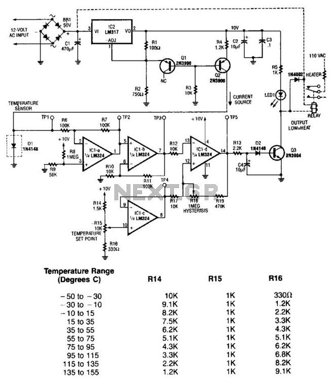
The LM35 temperature sensor outputs 10 mV/C for each degree Celsius above 0°C. At 20°C, the output voltage is calculated as 20 × 10 = 200 mV. The circuit consumes minimal power. Additionally, the load resistance should not be...
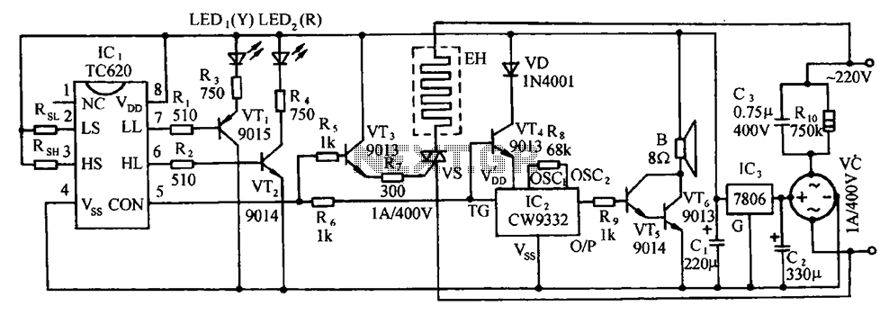
The circuit includes the TC620 temperature control circuit, the temperature indicator circuit, a thyristor-controlled heating circuit, a vocal music buck rectifier circuit, and the AC circuit. The TC620 temperature control circuit is designed to regulate temperature by monitoring the temperature...

An ambient light sensor circuit is a circuit that utilizes light intensity to perform various applications. An ambient light sensor circuit typically consists of a light-dependent resistor (LDR) or phototransistor that detects the intensity of ambient light. The sensor converts...

A biaxial magnetic field sensor application circuit is illustrated in the figure. This circuit utilizes a biaxial magnetic sensor HMC1002 along with two AMP04 operational amplifiers (A1, A2) to measure the magnetic field in both the X-axis and Y-axis...

Remote temperature measurements must be connected to the relevant test instrument using a cable. Typically, a three-core cable is employed: one core for the signal and two for the power supply. If a two-core cable is necessary, one of...