
I.F. Amplifier

The Intermediate Frequency (I.F.) amplifier described is a critical component in radio receiver systems, particularly for the 80M band. The modification involving the inclusion of Light Emitting Diodes (LEDs) in the source circuit of each MOSFET is notable for enhancing the performance of the amplifier. The LEDs introduce a fixed voltage drop, stabilizing the source voltage at approximately 2 volts. This stabilization is essential for achieving a broader Automatic Gain Control (AGC) range, which is crucial for maintaining signal integrity across varying input levels.
In this design, the I.F. transformer plays a pivotal role in signal processing. The primary winding consists of 18 turns, while the secondary winding features 4 turns. This specific turn ratio is indicative of the desired impedance transformation and voltage gain characteristics of the amplifier. The 18:4 turn ratio implies that the primary winding is designed to handle a higher voltage from the preceding stages, while the secondary winding steps down the voltage to a level suitable for further amplification or processing.
The choice of MOSFETs in this I.F. amplifier design is likely due to their high input impedance and fast switching capabilities, which are advantageous in high-frequency applications. The incorporation of the LEDs not only aids in voltage stabilization but also potentially provides visual feedback for circuit operation, allowing for easier troubleshooting and performance monitoring.
Overall, the modifications and design choices made in this I.F. amplifier reflect a thoughtful approach to enhancing receiver performance, ensuring that it can effectively manage signal variations and maintain clarity in communication.The I.F. amplifier is similar to the one used in the 80M receiver project . The original design has been modified by putting a couple of LED`s in the source circuit of each Mosfet. The voltage drop across the LED`s keeps the source voltage at about two volts. This results in a much greater AGC range. This arrangement was suggested by N6BIU. Thanks Jim. The I.F. transformer primary has 18 turns, the secondary winding has 4 turns. 🔗 External reference
Related Circuits
The microphone amplifier comprises an LM324 integrated circuit and two transistors. The LM324 is available in a 14-pin dual in-line package (DIP) and was acquired at a cost of Rs 6. It contains four identical operational amplifiers. The transistors...
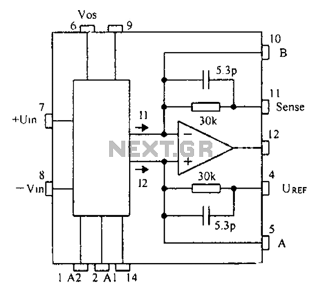
Based on the CNC programming, a gain instrumentation amplifier circuit diagram utilizing the PGA202/203 is presented. The PGA202/203 series of programmable gain amplifiers are designed for high-performance applications requiring precise signal amplification. These integrated circuits offer a wide range of...
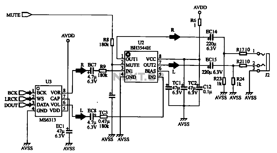
The MP4 audio circuitry consists of audio D/A converters and an audio amplifier combination circuit. This design features a straightforward circuit layout, making it suitable for integration into compact MP4 digital devices. The MP4 audio circuitry is designed to efficiently...
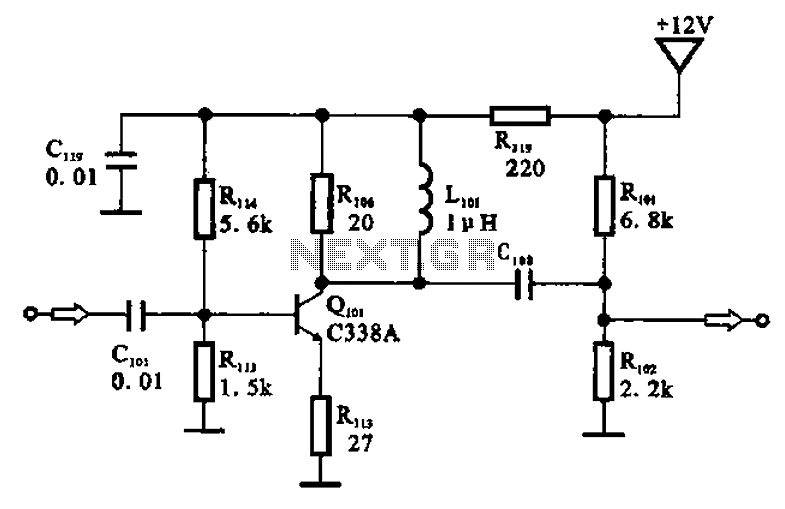
The amplifier circuit is designed as a pre-amplifier configuration. It utilizes transistor Q101 and other components such as inductor L101 and biasing elements. The transistor operates as a common emitter intermediate frequency (IF) amplifier. The IF signal is coupled...
The circuit was designed to create a modular Class A buffer preamplifier to isolate stages in an audio circuit. BF245 is a general-purpose N-Channel JFET used in this design. The modular Class A buffer preamplifier serves as an essential component...
Amplifying circuit diagram to enhance the output current and voltage. An amplifying circuit is designed to increase the amplitude of an input signal, resulting in a higher output current and voltage. This type of circuit is commonly utilized in various...