
A circuit diagram of an amplifier circuit to enhance the output current and voltage

An amplifying circuit is designed to increase the amplitude of an input signal, resulting in a higher output current and voltage. This type of circuit is commonly utilized in various electronic applications, such as audio systems, instrumentation, and communication devices.
The basic components of an amplifying circuit typically include transistors (BJT or FET), resistors, capacitors, and sometimes operational amplifiers (op-amps). The configuration of these components can vary based on the desired amplification characteristics, such as gain, bandwidth, and input/output impedance.
In a common transistor amplifier configuration, the transistor operates in its active region, where it can effectively amplify the input signal. The input signal is applied to the base (or gate) of the transistor, while the output is taken from the collector (or drain). Resistors are used to set the biasing conditions of the transistor, ensuring it remains in the active region during operation. Coupling capacitors may be employed to block DC components while allowing AC signals to pass through, thereby isolating different stages of amplification.
For further enhancement of performance, feedback mechanisms can be introduced. Negative feedback can stabilize the gain and improve linearity, while positive feedback can be used in specific applications to increase gain further. The choice of components and configuration will ultimately depend on the specific requirements of the application, including the desired frequency response and power handling capabilities.
In summary, an amplifying circuit is crucial for boosting signal strength in various electronic applications, and careful design considerations are necessary to achieve optimal performance.Amplifying circuit diagram to enhance the output current and voltage:
Related Circuits
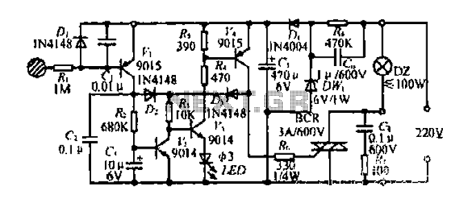
Diagram 2 depicts a shake tube circuit with a capacitance (C) and a trigger voltage rectifier filter element. The circuit includes a trigger voltage transistor amplifier (H), three pull tubes (n, U, v), and utilizes a thyristor as a...
This circuit is designed to drive a total of 42 LEDs, assuming a forward voltage of approximately 2.2V per LED and a forward current of around 21mA for adequate brightness. If the specifications of the LEDs differ significantly, modifications...
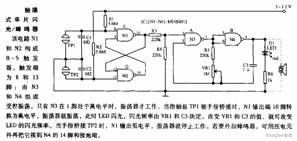
In the circuit, N1 and N2 form the RS flip-flop, with the trigger inputs located at pins 8 and 13. N3 and N4 create a controlled oscillator that operates only when pin 1 of N3 is high. When the...

Although analog and digital controllers may seem vastly different, their principles of operation are often quite similar. Therefore, popular analog tools like Spice can still be utilized to enhance common digital proportional-integral controllers through analysis, without the need for...
This type of design can produce a very high amperage current for a fraction of a second that can be used to do some useful work if properly harnessed. A point to remember is that Paul Baumann built his...

Here is a design for a temporary lamp circuit that is very helpful in emergency situations or in any application where there is limited time to turn off the lamp. Simply press the push button to perform a quick...