
IC Controlled Emergency Light With Charger Circuit

The IC-controlled emergency light circuit operates on a dual functionality principle, serving both as an emergency lighting solution and a battery charging system. The core components include an inverter circuit that converts the 12V DC battery voltage to 220V AC output, suitable for powering standard household appliances during power outages.
The operation begins with the detection of a mains failure. When the mains voltage drops below a certain threshold, the relay RL2 is triggered to switch to its de-energized state. This action connects the battery to the inverter circuit, enabling the inverter to generate 220V AC output. The inverter typically consists of a transformer and a switching mechanism, often using transistors or MOSFETs, to efficiently convert the DC voltage to AC.
Simultaneously, the circuit includes a battery charging mechanism that ensures the battery remains charged when mains power is available. The charger is designed with over-charge protection to prevent damage to the battery. This is typically achieved through a voltage regulation circuit that monitors the battery voltage and disconnects the charging current when the battery reaches its full charge capacity.
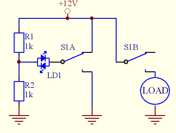
Switch S1 plays a critical role in the circuit by allowing manual intervention to enable or disable the inverter operation, providing flexibility in usage. Overall, this circuit design combines safety, efficiency, and reliability, making it an effective solution for emergency lighting needs.Here is the circuit diagram of IC Controlled Emergancy Light With Charger or simply 12V to 220V AC inverter circuit. The circuit shown here is that of the IC controlled emergency light. Its main features are: automatic switching-on of the light on mains failure and battery charger with over-charge protection.
When mains is absent, relay RL2 is in de-energized state, feeding battery supply to inverter section via its N/C contacts and switch S1 🔗 External reference
Related Circuits
Assistance is needed for a project involving the construction of a switch panel. The individual has a good understanding of 12V electrical wiring but is encountering difficulties with this specific task. The project involves designing a switch panel that can...
Described here is a very inexpensive solution to many phono-controlled applications like remote switching on, for instance, or activating a camera, tape recorder, burglar alarms, toys, etc. The circuit given here employs a condenser microphone as the pick-up. A...
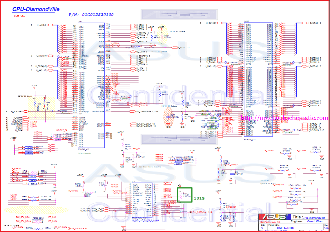
Laptop schematic circuit diagram for laptop repair and laptop BIOS password removal. The laptop schematic circuit diagram serves as a crucial resource for technicians and engineers involved in laptop repair and maintenance. This diagram provides a detailed representation of the...
This circuit can be utilized as a replacement for the single current-limiting resistor typically found in low-cost battery chargers. The alternative presented here is advantageous because it prevents the premature failure of nickel-cadmium (NiCd) batteries, which often occur after...
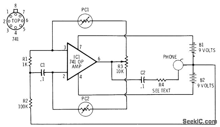
The 741 operational amplifier is configured as an audio oscillator using Radio Shack 276-677 photocells in the feedback circuits. When light strikes photocell PC1, its resistance decreases, resulting in a corresponding decrease in the frequency of the audio tone...
For successful circuit-building exercises, follow these steps: Measure and record all component values before constructing the circuit, selecting resistor values that are sufficiently high to minimize the risk of damaging any active components. In case of significant errors (greater...