
Ignition Coil Wont Spark from Mosfet but DOES spark By Hand

The circuit involves a 555 timer configured in astable mode to generate a pulse-width modulation (PWM) signal that drives the gate of a MOSFET. The output from the 555 timer is used to turn the MOSFET on and off at a frequency suitable for the ignition coil. The MOSFET acts as a switch, allowing current to flow through the ignition coil when activated.
In this setup, the ignition coil is connected to a power source, typically a battery. When the MOSFET is turned on, current flows through the ignition coil, generating a magnetic field. Upon turning off the MOSFET, the collapsing magnetic field induces a high voltage in the coil, creating a spark at the output terminal of the ignition coil.
To ensure proper operation, it is essential to select a MOSFET that can handle the required current and voltage levels. Additionally, protection components such as a flyback diode may be included across the ignition coil to prevent voltage spikes from damaging the MOSFET. Proper heat sinking for the MOSFET may also be necessary to manage thermal dissipation during operation.
The timing characteristics of the 555 timer should be adjusted to achieve the desired spark frequency, which can be fine-tuned by changing the resistor and capacitor values in the 555 timer circuit. Overall, this configuration provides a reliable method for generating sparks using an ignition coil and a MOSFET controlled by a 555 timer.I`m trying to get an ignition coil to create sparks running it with a Mosfet powered by a 555 timer. The Mosfet is definitely switching. I checked it.. 🔗 External reference
Related Circuits
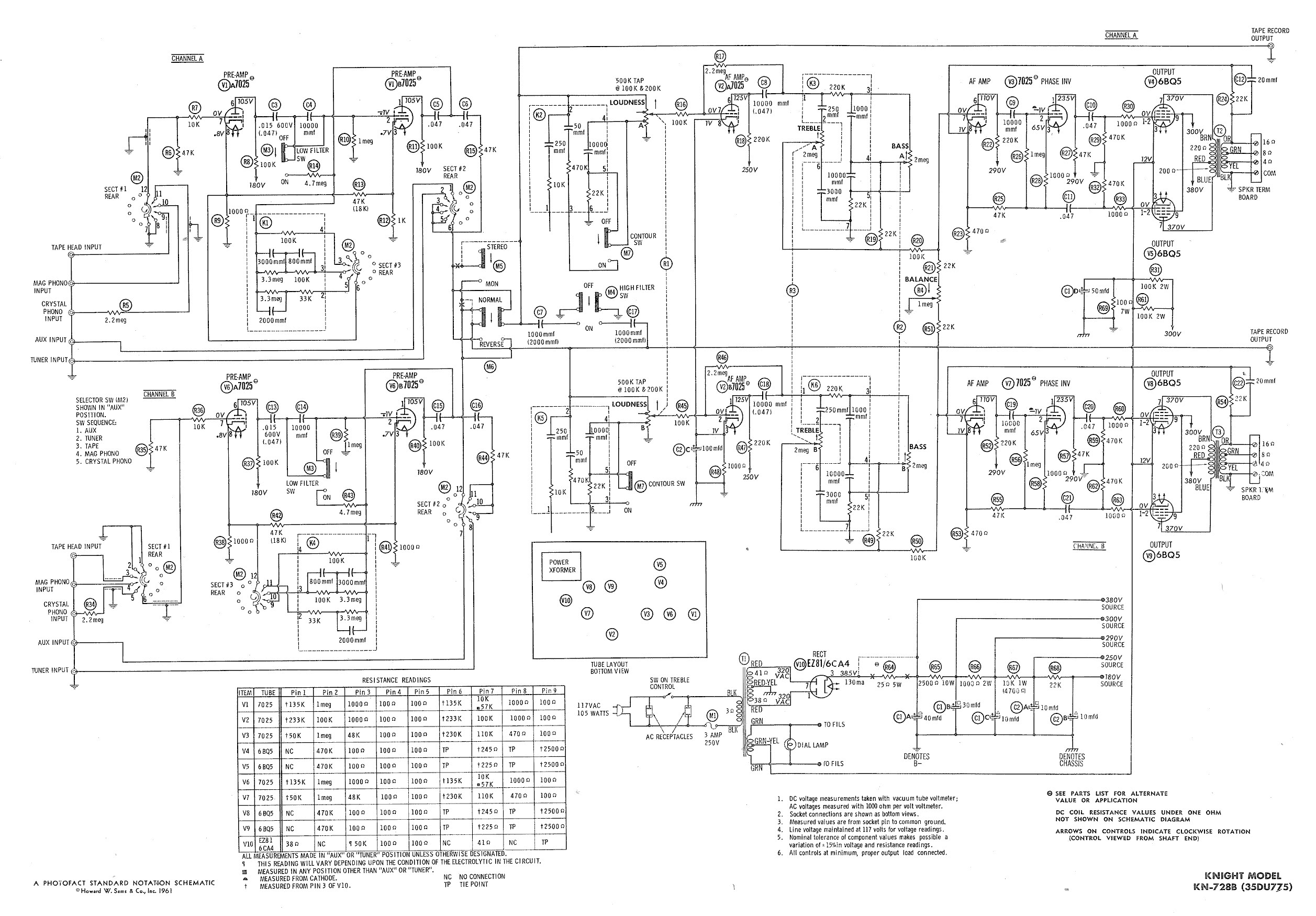
Ty - Concerning the updated schematic of the AF/PI stage, it appears that resistor R45 is not present. Additionally, the disk capacitor bypassing R44 is marked as 68nF750 with a tolerance of 10%, which is presumed to be the...
This document presents an overview of the hardware design of the Handy Cricket. The Handy Cricket is a compact electronic device designed for educational and recreational purposes, primarily aimed at children. The hardware design incorporates various components that work together...
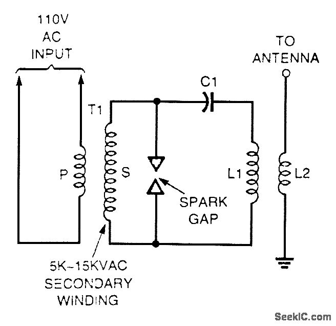
A high-voltage current-limiting transformer (T1) provides power to a basic LC tuned circuit. As capacitor C1 charges to approach the maximum output voltage of the transformer, the air gap in the spark gap breaks down, thereby completing the circuit...
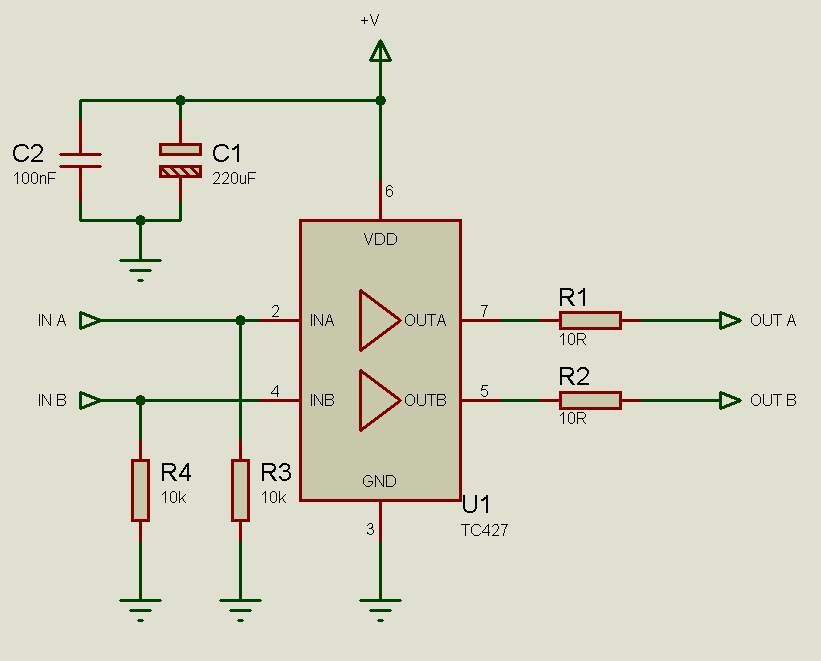
MOSFETs cannot simply be connected to the drive signal and expected to function correctly. Due to their construction, driving MOSFETs can be complex, particularly for beginners. Many users frequently seek assistance with MOSFET drive issues on various blogs, websites,...
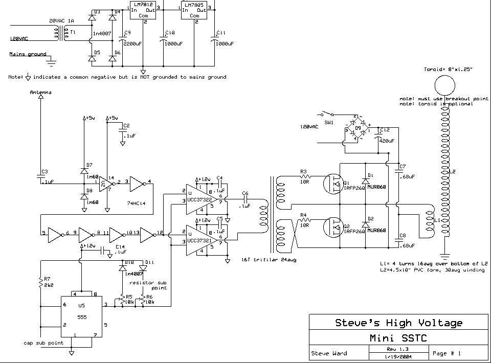
The design is a clone of Steve Ward's MiniSSTC circuit; the schematic is reprinted here with credits to Steve Ward. This circuit performs very well for a low power and simple SSTC. The design is based on Steve's final...
This inverter circuit can provide a stable 230V output voltage. The operating frequency is determined by a variable resistor (VR1) and is typically set to 60 Hz. Various off-the-shelf transformers can be utilized, or custom-wound transformers can be created...