
Increasing the power rating of zener diodes

The described circuit configuration employs a power transistor to amplify the Zener voltage output, allowing for the use of lower-rated Zener diodes in applications that demand higher power levels. The selection of transistors is critical: for lower power requirements, the ASZ 15 or AY9140 are suitable choices for Q1, while the 2N2955 serves as a robust option for Q2. In contrast, for higher power demands, the ASZ18 or 2N2955 can be used for Q1, with Q2 being fulfilled by either the 2N3055 or AY8149, both of which are capable of handling increased current loads.
The integration of a heatsink is essential for thermal management, as power transistors dissipate significant heat during operation. The design allows for the transistors to be mounted directly onto a metallic chassis, which not only secures the components but also enhances heat dissipation by utilizing the chassis as a passive heatsink. This configuration promotes efficient thermal management, ensuring the reliability and longevity of the circuit by preventing overheating.
Overall, this circuit design exemplifies an effective method to achieve higher power Zener voltage outputs while maintaining manageable thermal conditions through careful component selection and efficient heatsinking strategies.A power transistor can be used to provide a high powered zener voltage from a low wattage zener. A 400 mW zener can be used where a 10 watt zener is required or a 1 W zener can be used where a 50 to 80 watt zener is required by using appropriate transistors for Ql and Q2 in the circuits shown. Where low rating is required, Ql would be an ASZ 15 (germanium) or an AY9140 (silicon). Q2 could be a 2N2955 (silicon). For higher powers, Ql should be an ASZ18 (germanium) or a 2N2955 (silicon) and Q2 a 2N3055 (silicon) or an AY8149 (silicon).
A heatsink on the transistor is required. The circuit in A has the advantage that power transistors can be bolted directly on to a chassis which may serve as a heatsink.
Related Circuits
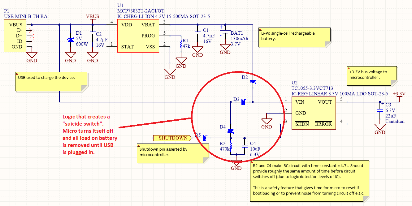
Overview Disabling Sections of a Circuit The "Suicide Switch" Overview Power management is a significant design consideration for battery-powered devices. Power management is a crucial aspect of circuit design, particularly in battery-powered applications where energy efficiency directly impacts the operational...
The schematic diagram originates from a 70W switching power supply utilizing the KA2S0880 IC. This power supply is designed for a 70W stereo amplifier and incorporates all necessary components for its primary operation. The KA2S0880 chip is known for...
This amplifier is designed to be as flexible as possible, with no bad habits. Indeed, it will operate stably with supply voltages as low as +/-5V (completely pointless, but interesting), all the way to the maximum supply voltage of...
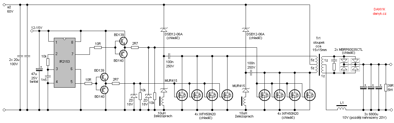
Occasionally, a low voltage power supply capable of delivering very high currents (hundreds of amperes) is required for applications such as spot welding, heating or melting metals, starting vehicle engines, or conducting various physical experiments. A decision has been...
The "R-h sampling circuit limit order" aims to reduce the sampling resistor. A DC voltage level can be positioned between the components. The circuit includes a line amplifier that allows for magnification adjustments and is designed to protect against...
This regulated power supply was built as a simplified outboard version of a PSU in my first phono stage. Replacing hexfreds with tube rectifier eliminates the need for power-on sequencing. Chassis (salvaged from a hospital laser PSU) size is...