
InfiniBand Bus Description

Higher bandwidth connections in InfiniBand technology are facilitated by the aggregation of multiple pairs, either in groups of four or twelve, allowing for substantial data throughput of up to 3 gigabits per second in a full-duplex configuration. This high-speed communication is applicable across various mediums, including backplanes, copper wiring, and fiber optic cables. The standard impedance for both the printed wiring board (PWB) and cable interfaces is set at 100 ohms, which is critical for maintaining signal integrity and reducing reflections.
InfiniBand's hot-swappable capability ensures that connections can be made or broken without the need to power down the system, enhancing system reliability and uptime. The data transfer rate is defined at 250 MBytes/sec, which translates to a high signaling frequency of 2.5 GHz, utilizing 8B/10B encoding to ensure efficient data transmission by converting 8 bits of data into 10 bits for transmission.
The structure of an InfiniBand packet is meticulously defined, starting with a Start-of-Frame (SOF) marker and concluding with an End-of-Frame (EOF) marker. The packet's header is composed of two essential components: the Routing Header, which directs the packet through the network, and the Transport Header, which contains information about the transport layer. Following the header is the Packet Payload, which carries the actual data.
To ensure data integrity, two types of Cyclic Redundancy Codes (CRC) are employed. The Invariant CRC (ICRC) is used for packets that do not change as they traverse the network from source to destination, while the Variant CRC (VCRC) applies to packets that may experience modifications at different links. Additionally, fill frames are utilized to maintain the timing and spacing of packets within the transmission stream.
Jitter specifications are critical for maintaining the quality of the signal. The maximum allowable Deterministic Jitter (JD) is specified at 0.17 UI, without the application of pre-emphasis techniques, while the total jitter (JT) allowed is capped at 0.35 UI. This control over jitter is essential for ensuring reliable data transfer and minimizing errors.
The components of the InfiniBand system are typically enclosed within a metal casing, which serves the dual purpose of providing structural support and shielding against electromagnetic interference (EMI). While the thickness of the PWB is not explicitly defined, it is essential that the board fits within the parameters set by the EMI shielding case, ensuring compliance with electromagnetic compatibility standards. This design consideration is vital for the overall performance and reliability of the InfiniBand system in high-speed data communication environments.Higher bandwidth connections are made by grouping 4 or 12 pairs together, for up to 3 GB/s full-duplex connections. InfiniBand is designed to be used over a Backplane, Copper wire or Fiber. The impedance for the PWB interface or cable interface is 100W. All inter-connections are Hot-Swappable on InfiniBand. The specification defines a data rate of 250MBytes/sec for both electrical and optical signaling. That`s a 2. 5GHz signaling speed using 8B/10B [10 bits = 1 byte] Each IBA Packet [InfiniBand Architecture] begins with a Start-of-Frame [SOF], and ends with an End-of-Frame [EOF]. The Header field is made up of a Routing Header and a Transport Header. The Packet Payload follows the Header field. Two different Cyclic Redundancy Code [CRC] fields follow the Payload; ICRC [Invariant CRC] and VCRC [Variant CRC].
The Invariant CRC field covers the packets that do not change from source to destination, while the Variant CRC filed covers packets from link to link. Fill frames are used between packets. The maximum allowable Deterministic Jitter [JD] from the driver is 0. 17 UI [without pre-emphasis]. The Total Jitter [JT] allowed from the driver is 0. 35 UI. They reside with in a metal case to provide EMI shielding. The thickness of the PWB isn`t really defined, as long as it resides with in the EMI defined case. 🔗 External reference
Related Circuits
PIC C Compilers are utilized to compile source code, leveraging the extensive built-in functions offered by these compilers. A single C statement can produce multiple pages of PIC RISC instructions, eliminating the need for manual coding. CCS charges $125...
The Controller Area Network (CAN) bus line, also known as a control device LAN, is recognized for its high performance, reliability, and unique design. Initially developed by Bosch in Germany for automotive applications, the CAN bus has expanded into...
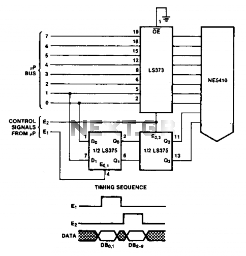
The double latch technique ensures that valid data is latched to the Digital-to-Analog Converter (DAC) until it is updated by the E2 pulse. The timing of this process will depend on the specific processor utilized. The double latch technique is...
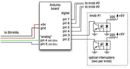
BlinkMs are entertaining devices that function as small network components, each assigned a unique address on an I2C network. The potential of BlinkMs is particularly evident in their ability to simplify the control of multiple RGB LEDs. For a...
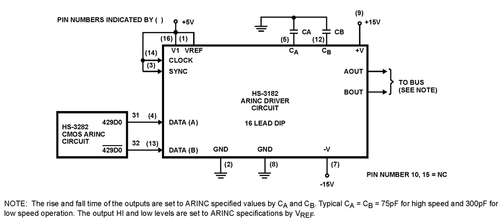
The HS-3182 is a monolithic dielectrically isolated bipolar differential line driver designed to meet the specifications of ARINC 429. This device is intended to be used with a companion chip, the HS-3282 CMOS ARINC Bus Interface Circuit, which provides...
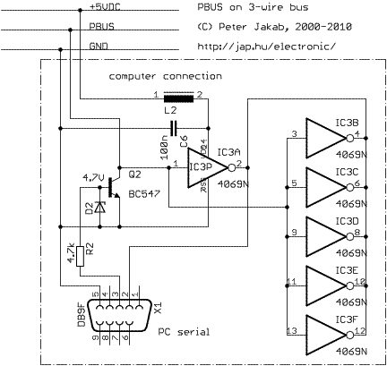
PBUS is an RS485-like multi-drop bus for interconnecting PIC and other microcontroller-driven devices. Protocol and software is written by Jap. Just include a separate pbus library file into your project and add your command handlers for the specific device...