
Infrared automatic faucet circuit diagram

The circuit operates as a comprehensive control system for various applications. The infrared emitter generates a modulated infrared signal at a frequency of 38 kHz, which is optimal for many infrared communication applications, ensuring minimal interference from ambient light sources. The 555 timer is configured in astable mode, with the oscillation frequency being adjustable through the resistors and capacitor connected to it.
The infrared receiver circuit is designed to detect the emitted signal. The infrared receiver tube (VD2) captures the infrared light, while the CX20106 serves as a demodulator, processing the received signal to trigger subsequent actions in the circuit.
The water valve control circuit allows for automation of water flow using controlled gates (F1 and F2) to manage the opening and closing of the valve. The drive tube (VT1) amplifies the control signal, while relay (K1) acts as a switch to physically control the water valve.
Similarly, the lamp control circuit operates in a parallel fashion, where control gates (F3 and F4) manage the operation of a lamp. The drive tube (VT2) amplifies the control signal for the relay (K2), enabling or disabling the lamp based on the received infrared signal.
This circuit design demonstrates versatility in controlling multiple devices using infrared communication, making it suitable for remote control applications in various electronic systems.The circuit is composed of the parts below: (1) infrared emitterThe multi-harmonic oscillator is comoposed of 555 circuit. The oscillation frequency is decided by value of the RP1, R1, C1. The circuit`s oscillation frequency is 38kHz. (2) infrared receiver circuitThe circuit is composed of infrared receiver tube VD2 and CX20106. (3) water valve con trol circuitThe circuit is composed of controlled gate F1, F2 and drive tube VT1 and relay K1. (4) lamp control circuitThe circuit is composed of the control gate F3, F4, drive tube VT2 and relay K2. 🔗 External reference
Related Circuits
This circuit is a motion detection sensor that utilizes a light source and detector as an infrared motion detector. The motion sensor employs an infrared LED and a phototransistor. Since it relies on light, the sensor's sensitivity can be...
The following circuit illustrates a Solar Tracker Circuit Diagram. This circuit is based on the LM339 integrated circuit. Features include a 10nF ceramic capacitor (103z) and a 1MΩ resistor. The Solar Tracker Circuit utilizes the LM339 quad comparator IC to...
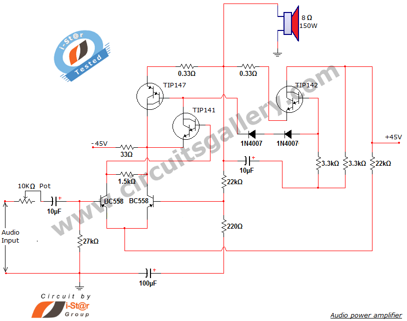
This document presents a new audio power amplifier schematic utilizing TIP darlington pair transistors. It is suitable for both home audio and car audio amplifiers. The TIP142 and TIP147 darlington pair transistors create a push-pull high-power amplifier configuration, while...
The circuit presented is a standard Colpitts oscillator, commonly utilized in many amateur radio homebrew transmitters. This specific circuit is designed to operate effectively within a frequency range of 1500 kHz to 8000 kHz. To accommodate lower frequencies, it...

This circuit is designed as a pocket-sized, high-performance audio oscillator. It can operate using a battery-powered version, which is feasible at a very low cost by utilizing a single quad op-amp to provide the entire active circuitry. The design...
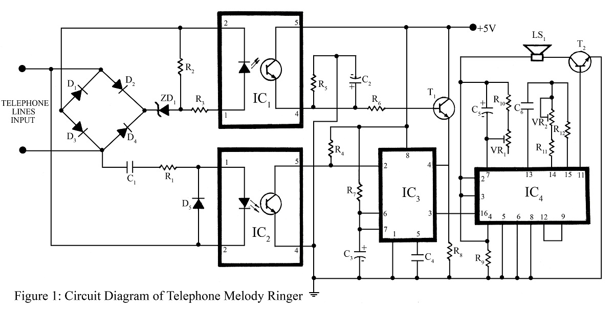
The telephone project described here is a telephone ringer that produces pleasant tunes when a call is received. The tunes generated by this telephone ringer are more melodious and soothing compared to those of traditional telephone instruments and piezo...