
Infrared IR Receiver Circuit

The Infrared IR Receiver circuit is a practical application of optical communication technology. It utilizes a phototransistor as the primary sensor, which is sensitive to infrared light emitted by an IR LED in a remote control. When the IR LED transmits a signal, the phototransistor detects the light and converts it into an electrical signal. This signal is often weak and requires amplification to be effectively processed.
The operational amplifier (Op-Amp) is crucial in this circuit, as it amplifies the weak signal from the phototransistor and inverts it if necessary, ensuring that the microcontroller receives a clear and robust signal for further processing. The microcontroller interprets the amplified signal, determining which button was pressed on the remote control based on the encoded data received.
The LCD module, compliant with the HD 44780 standard, displays information regarding the button presses. This module interfaces with the microcontroller using a parallel data connection, allowing for a straightforward method to present user feedback. The 16x2 configuration of the LCD provides a clear display format, showing the status of the controller in real-time.
In addition to the LCD, the inclusion of LEDs enhances user interaction by providing visual feedback. These LEDs light up in response to specific button presses, offering immediate confirmation of the command received from the remote control. This added functionality not only aids in debugging but also improves the overall user experience by providing intuitive feedback.
Overall, the Infrared IR Receiver circuit is a well-integrated system that combines various electronic components to achieve effective remote control functionality, demonstrating the principles of data transmission and processing in electronic circuits.The Infrared IR Receiver circuit is not particularly unique. The main components are the phototransistor, the microcontroler and the amplifier. If you can understand how these three devices transfer data, then you should have no problem getting the circuit to work on your own. This is where the true magic happens. The phototransistor receives t he digitally encoded data from an IR emitting diode inside of the Direct TV Remote. The Op-Amp amplifies and inverts the signal which is finally passed to the microcontroller. This is the LCD used to output the current status of which button has been pressed. It`s mainly here to verify that the controller is working. This 16x2 module works off of the HD 44780 parallel data standard. See the Interfacing LCD ‡’ PIC tutorial for more information on exactly how this device works. Similar to how the LCD is used, the LEDs are just there for verification purposes and to add some more functionality to the controller. The LEDs will switch on or off when you press one of the colored buttons on the remote control. 🔗 External reference
Related Circuits
This circuit functions as a camera switch, allowing multiple cameras to be connected to a single monitor. It can operate in both manual and automatic modes. In automatic mode, the circuit utilizes a 555 astable multivibrator to generate a...
The applet shows a simulation of Chua's circuit, plotting the voltage measured across C1 against the voltage measured across C2. This corresponds to the display on an X-Y oscilloscope with probes connected across these capacitors. The initial values of...
This project involves a straightforward and practical 12V power supply circuit utilizing the LM7812 integrated circuit (IC). The LM7812 is a three-terminal fixed voltage regulator IC housed in a TO-220 package. It incorporates several built-in features such as thermal...
Ambient light is increasingly being utilized as an energy source. To assist designers in developing such systems, this circuit effectively measures ambient light intensity across four decades of measurement. The design is cost-effective, and with the sensor housed in...
This infrared alarm barrier is designed to detect individuals passing through doorways, corridors, and small gates. The transmitter emits a beam of infrared light that is invisible to the human eye. When the light beam is interrupted by a...
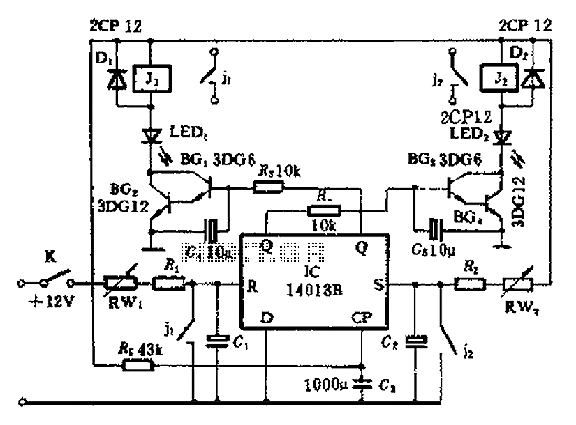
The timing control circuit is a sequential circuit that allows for sequential timed control of two switches. The control time can be adjusted from a few seconds to several tens of seconds. If mechanical control is applied for reciprocating...