
Infrared light trap circuit

The infrared light valve circuit is designed to provide an effective alarm system, utilizing a transmitter and receiver configuration that minimizes interference from ambient light. The transmitter employs a NE 555 timer (IC1), which is configured in astable mode to generate a series of pulses. These pulses are directed to an infrared LED (D1, LD274), which emits infrared light at a frequency determined by the variable resistor P1 (10 kOhm). The frequency of these pulses can be adjusted to optimize the performance of the system.
On the receiving end, a phototransistor (T1, BPW40) detects the infrared light emitted by the LED. The output pulses from the phototransistor are coupled through a capacitor (C4, 47 nF) to the positive input of an operational amplifier (IC2, LM 741). The operational amplifier is configured with a feedback network that includes resistors (R1, R2, R3, R4, R5, R6, R7, R8, R9, R10, R11) and capacitors (C1, C2, C3, C6, C5) to stabilize the gain and set the frequency response of the circuit. The RC network between the output and inverting input of the op-amp ensures that the circuit maintains a low frequency response, with a cutoff around 7.2 kHz, which is critical for minimizing false triggers from unwanted noise.
When the phototransistor receives the infrared pulses, it generates a corresponding output voltage that is amplified by the operational amplifier. The amplified signal is then used to drive a transistor (T2, BC547), which controls a relay (RE1). The relay acts as a switch, allowing for the activation of an alarm or other devices when the infrared beam is interrupted.
To ensure proper operation, it is essential to position the infrared LED and phototransistor so that they are aligned with each other, allowing for optimal light transmission and reception. The adjustment of P1 allows for fine-tuning of the sensitivity of the circuit, ensuring that the relay activates only when the infrared signal is disrupted. The overall design provides a robust solution for alarm systems, leveraging the simplicity and reliability of infrared technology.This infrared light valve has more parts, so it works better and more reliable for alarms. The circuit responds less ambient light. The light valve consists of a transmitter and a receiver. The transmitter consists of a NE 555 which provides pulses to the infrared LED (D1) are fed. The frequency of the pulses is set to P1. On the receiver side we see the photo transistor T1 receives the pulses from D1. The pulses through C4 to the positive input of op amp IC2 led. Between the output of IC2 and the minus input is an RC network that ensures the lowest at about 7.2 kHz amplitude issues. R1 = 1 kOhm R2 = 2.7 kOhm R3 = 470 ? R4 = 100 kOhm R5, R6 = 270 kOhm R7, R8 = 47 kOhm R9 = 270 ? R10 = 180 kOhm R11 = 10 kOhm P1 = 10 kOhm C1 = 15 nF C2 = 10 nF C3, C6 = 100 uF C4, C5 = 47 nF C7 = 2.2 uF C8 = 4.7 uF Then the gain of the 741 the least inhibited. When the pulses of the transmitter frequency which is the output voltage of 741 the highest. This allows guiding and T2 the relay is energized. The correct adjustment is simple. Place the phototransistor and the infrared LED so opposed that they can see each other. Control over P1 such that the relay picks up. D1 = LD274 D2, D3, D4 = 1N4148 T1 = BPW40 T2 = BC547 IC1 = NE 555 IC2 = LM 741 RE1 = 1 x relay switch
🔗 External reference
Related Circuits
The example below illustrates the use of an operational amplifier (op-amp) as an audio amplifier in a basic intercom system. A small 8-ohm speaker is utilized as a microphone, which is connected to the op-amp input through a 0.1...
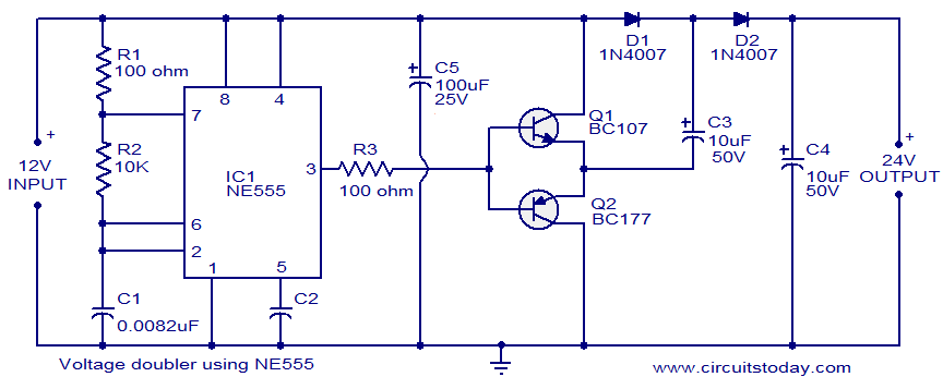
The circuit diagram of a simple voltage doubler using the NE555 timer is presented. In this configuration, the NE555 IC operates as an astable multivibrator at approximately 9 kHz. The bases of two transistors, Q1 and Q2, are connected...
A CI-22BG tube and a CI-3BG tube were purchased for a total of 16G. Due to the lack of radioactive materials for testing the Geiger counter, a piece of radioactive Fiesta dinnerware was ordered from eBay. Red Fiestaware historically...
The electronic designs for the two animatronic mouths are presented below. The first design is for the articulated mouth, with additional servos for the eyebrows and eyes. The second design is for the LCD mouth, which closely resembles the...
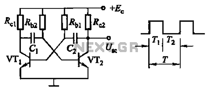
Common non-sinusoidal oscillator circuit, waveform and frequency formula - square wave oscillator - self-excited multivibrator The common non-sinusoidal oscillator circuit, specifically the square wave oscillator, is a fundamental electronic circuit utilized to generate square wave signals. It operates based on...
The circuit utilizes a 555 timer integrated circuit (IC) configured as an astable multivibrator. The flashing rate can be adjusted from very fast to a maximum of once every 1.5 seconds by changing the setting of the preset variable...