
Animatronic Mouths Circuit

The schematic for the animatronic mouth designs consists of two primary configurations: one for the articulated mouth and another for the LCD mouth, each serving distinct functions within the animatronic system. The articulated mouth design utilizes the HS-485HB servo, which is capable of providing robust motion for the mouth's articulation, while the additional servos for the eyebrows and eyes enhance the expressiveness of the animatronic face.
The HS-55 servos are employed for the smaller movements required by the eyebrows and eyes, ensuring a wide range of motion and responsive control. The choice of the 7805 voltage regulator is crucial, as it stabilizes the power supply to the microcontroller and servos, ensuring consistent operation. The dual regulator approach not only safeguards the system from potential overloads but also improves the reliability of the power supply to the more demanding HS-485HB servo.
The PIC 18F452 microcontroller is central to the control logic of the animatronic system. It processes inputs and generates outputs to control the servos. The use of PORTD for servo control allows for precise timing and coordination of movements, which is essential for creating realistic animations. The microcontroller's programming can be tailored to implement complex movement patterns, allowing for a wide range of expressions and behaviors.
The LCD display serves as a visual interface, providing feedback or information relevant to the animatronic's operation. The backlight control via PORTA enhances visibility and usability in various lighting conditions. While the design complexity increases with the wiring needed to access the LCD's character arrays, utilizing the 4-bit data bus option can significantly reduce the number of connections required, simplifying the overall design.
In summary, the electronic schematics for the animatronic mouths integrate various components and systems to create a responsive and expressive animatronic face. The careful selection of servos, voltage regulators, and microcontrollers, along with thoughtful design considerations for power management and control, culminates in a sophisticated and functional animatronic system.The electronic designs for the two animatronic mouths can be seen below. The first design is for the articulated mouth, the extra servos are for the eyebrows and eyes. The second design is for the LCD mouth. It is very similar to the custom characters on an LCD tutorial`s schematic. The most important parts seen in these two electronic schematics are the HS-485HB Servo, 7805, PIC 18F452 and 16x2 LCD Display. The power supply circuit is seen in two places. One for powering the PIC and most of the small HS-55 servos for the eyes and eyebrows. The second place, is powering the newly added HS-485HB servo for articulating the mouth. This servo requires more power from the regulator, so the easiest option was to add a second regulator for safety. The 18F452 PIC`s PORTD is used for controlling all of the servos. Each servo is driven by a specific pin on the PIC meaning we have independent control over every servo`s movement at any given time.
There are now a total of 7 servo motors used to actuate the movement seen in this animatronic face. 2 servos are used for the eyebrows, 4 servos for the two eyes and now one servo will be used to move the animatronic mouth up and down. The standard +5v regulator circuit seen in many of my tutorials and projects will be used to provide power to the LCD and the PIC.
This regulator converts the battery`s +12v down to +5v which our digital electronics require. To drive the LCD and control the backlight, a PIC 18F452 microcontroller will be used. This microcontroller is seen in many of my projects and is very easy to program for and to work with. The interface to the LCD from the Microcontroller uses PORTD for passing Data, PORTB for control signals and PORTA for backlight control.
This design requires more wiring in order to access the LCD`s character arrays, however it could be reduced if we used the reduced 4-bit data bus option with the LCD. 🔗 External reference
Related Circuits
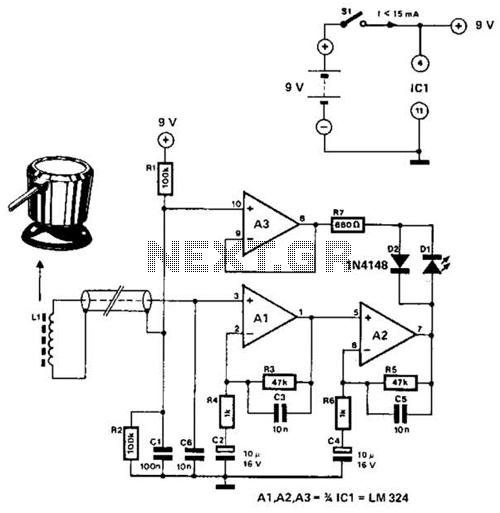
The circuit utilizes the principle that in an RL circuit, the pulse width across the inductor is proportional to the inductance. This circuit indirectly measures the inductance using a digital voltmeter (DVM). The measurement range is approximately 5 to...
The 10-meter 27MHz continuous wave (CW) radio amplifier is equipped with the VN66AF transistor produced by Siliconix, which offers several advantages: it is inexpensive, provides excellent dielectric insulation, and has high gain. The VN66AF is utilized as an RF...
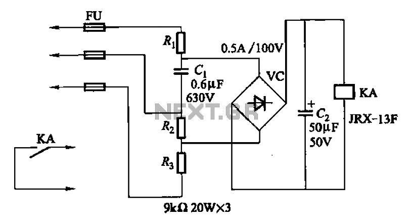
A capacitor C1 and resistors R1-R3 form a negative sequence voltage filtration device. The resistors and capacitors must meet the following requirements: R1, R2, R3 = 5.5/C1 (KN). The relationship between the resistance and capacitance values is arbitrary. Capacitor...
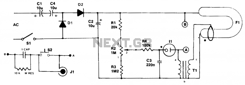
Initially, the neon and xenon lamps do not conduct and behave like very high (almost infinite) resistance. Capacitors C1 and C4, in conjunction with diodes D1 and D2, form a voltage doubler circuit, allowing C2 to charge up to...
The DTMF codec stands for dual-tone multi-frequency codec. The multiple-channel infrared remote control switch circuit that incorporates the DTMF is depicted in the figure. It consists of an infrared remote control signal emitter, an infrared receiving signal amplifier, a...
The 22-watt amplifier is straightforward to construct and cost-effective. This circuit can serve as a booster in a car audio system, an amplifier for satellite speakers in a surround sound or home theater setup, or as an amplifier for...