
Infrared receiver circuit

The infrared receiver circuit functions by utilizing a series of key components to effectively capture and process remote control signals. The BP104 photodiode is crucial for detecting infrared light emitted by remote control devices. When the infrared light strikes the photodiode, it generates a small current proportional to the intensity of the incoming light. This current is then amplified by the transistor VT1, which increases the signal strength to a level suitable for further processing.
The TDA4050B integrated circuit plays a significant role in the signal processing chain. It is designed to amplify the received signal, filter out noise, and shape it for accurate output. The integrated circuit's architecture includes various stages that ensure the signal integrity is maintained throughout the processing. After amplification and filtering, the shaped output signal is available at specific pins of the TDA4050B, which can then be connected to other components or systems for further use, such as controlling devices or systems based on the remote control input.
This circuit can be utilized in various applications where remote control functionality is required, such as in televisions, audio systems, and other consumer electronics. The design emphasizes reliability and performance, ensuring that the remote control signals are accurately received and processed, allowing for seamless user interaction with electronic devices.Shown as an infrared receiver circuit. The figure shows that the circuit is mainly composed of an infrared remote control signal switching circuit vri and signal amplification, filtering and rectifying integrated circuits TDA4 () 50B and other parts of. BP104 sense infrared photodiode infrared diode emitting an optical signal, BP104 will optical signal into a current signal, the signal after amplification by VT1 is fed TDA4050B pin, the remote control signal received by the integrated circuit amplifies, filters after shaping and output by the remote control signal feet.
Related Circuits
The transmission circuit for inductive wireless headsets must be securely mounted on a wall or ceiling, limiting its outdoor usability, which is a significant disadvantage of inductive wireless headphones. In contrast, infrared wireless headsets utilize a compact infrared transmitter...
This is a stereo power amplifier circuit that operates at up to 22W per channel, resulting in a total output of 2x22W. A few external components are required to support the main component, the TDA1554. A heatsink on the...
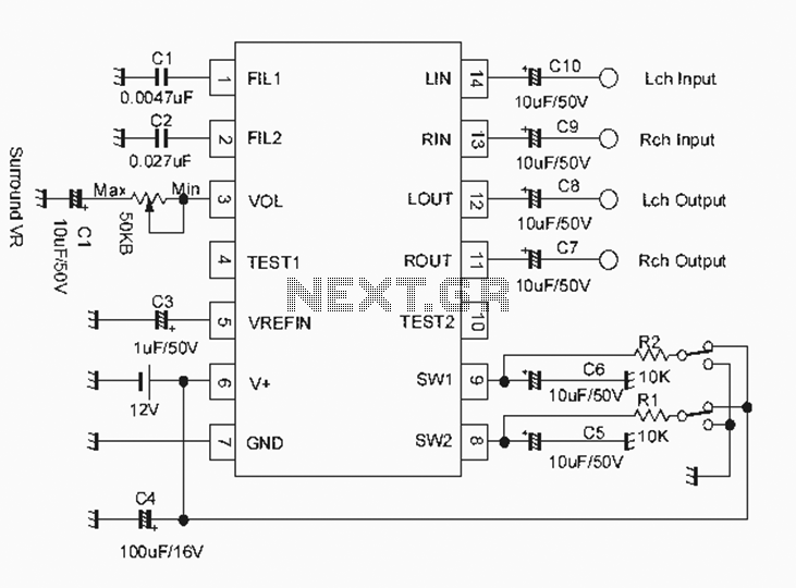
The NJM2701 3D surround sound audio processor integrated circuit can be designed into a very simple 3D surround sound system. The NJM2701 reproduces 3D surround sound using only two speakers and is suitable for various audio applications, including micro-components,...
Hello everyone, I am not well-versed in electronics, so I would appreciate it if someone could create a diagram for me. I would like to modify a circuit so that it can dial a number using speed dial and...
The amplification of this circuit is approximately 12,000 times, with a bandwidth ranging from 0.5 to 14 MHz. The input resistance is 700 ohms, while the output resistance is 35 ohms (measured at 5 MHz). The output noise level...
The performance of this sensitive ultrasonic receiver is impressive. It allows users to listen to various sources of ultrasonic sounds, including bugs, bats, and engines. The circuit utilizes a piezo tweeter as an ultrasonic microphone, with amplifier stages Q1...