
Infrared Remote-Control Tester Circuit

The infrared remote-control tester circuit is designed to detect infrared signals typically emitted by remote controls. The core component, a PN-type solar sensor, is sensitive to light variations, making it suitable for detecting both infrared and visible light. The connection to a Darlington amplifier, formed by transistors Q1 and Q2, allows for significant amplification of the small current generated by the sensor.
Resistor R1 serves as a biasing component, ensuring that the transistors operate efficiently within their active region. The variable resistor PI is crucial for adjusting the sensitivity of the circuit, allowing the user to fine-tune the detection threshold based on ambient light conditions and the distance from the infrared source.
The output from the Darlington amplifier is taken from the collector of Q1, where it drives a red LED, providing a visual indication of infrared signal detection. The connection to transformer T1 is significant as it steps up the low-voltage signal to a higher voltage suitable for driving a piezoelectric disc. The piezo disc is responsible for producing an audible clicking sound, which serves as an alert when the sensor successfully detects an infrared signal.
To enhance the performance of the infrared sensor and minimize false triggering from visible light, the incorporation of an IR filter, such as the Wratton #87, is advisable. This filter selectively allows infrared wavelengths to pass through while blocking a substantial portion of visible light, ensuring that the circuit responds primarily to infrared signals. Overall, this circuit provides an effective means of testing infrared remote controls, with both visual and audible feedback mechanisms. The infrared remote-control tester uses a sensitive PN-type solar sensor that is connected directly to a Darlington amplifier made up of transistors Q1 and Q2. Biasing is provided by R1 and PI, a variable resistor that serves as a sensitivity control. The collector lead of Q1 is the output lead of the Darlington amp, and it is connected to a red LED and the primary of transformer Tl.
The function of Tl is to convert the low-voltage output signal to a level high enough to drive a small piezo disc. That disc makes a clicking sound when the sensor picks up an infrared signal that is varying in frequency or amplitude.
The infrared sensor will also pick up visible light. The use of an IR filter (Wrat- ton #87) is recommended.
Related Circuits
This is a single-channel (on/off) universal switch that can be used with any infrared remote control operating within wavelengths of 850-950 nm. The single-channel universal switch functions as a simple on/off control mechanism, allowing users to operate electronic devices remotely...
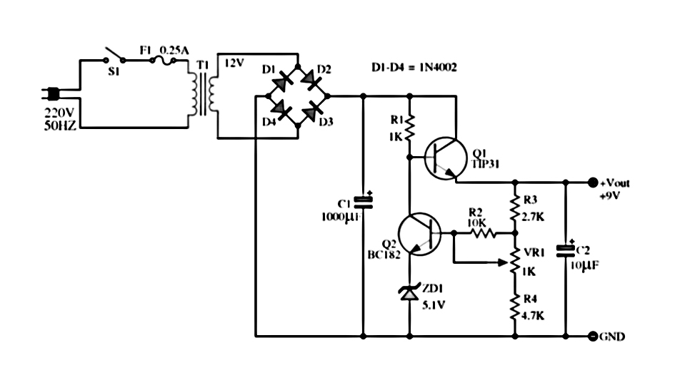
The power supply described utilizes a regulator composed of two NPN transistors. One transistor functions as the power regulator, while the other controls the output voltage. This power supply offers an adjustable output voltage range of 6-12 VDC. The...
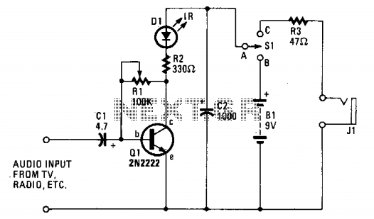
The ultra-simple one-transistor IR transmitter is designed to transmit sound from any 8 or 16-ohm audio source, such as a TV, radio, or tape recorder, using an infrared beam of light. The one-transistor infrared (IR) transmitter circuit operates by modulating...

Delta connection motor phase failure protection circuit is illustrated in the figure. Its protective function involves three resistors, R1, R2, and R3, which are connected to form an artificial neutral point. When a motor phase failure occurs, an offset...
This circuit utilizes a single 555 Timer IC along with a small transformer to generate high voltage for testing zener diodes with voltage ratings up to 50VDC. The 555 timer operates in astable mode, with the output from pin...
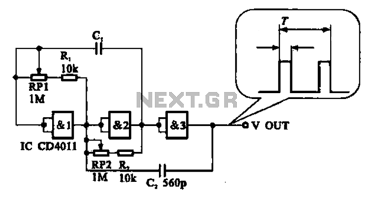
An adjustable pulse generator circuit is presented, which produces a periodic signal with independently adjustable pulse widths. The electrical path allows for modifications to the signal period through the adjustment of RP1. Additionally, RP2 can be altered to change...