
Adjustable pulse generator circuit

The adjustable pulse generator circuit typically consists of a few key components: resistors, capacitors, and operational amplifiers or timers, such as the 555 timer IC. The circuit operates by generating a square wave output, where the frequency and duty cycle can be modified according to the desired application.
In this configuration, RP1 serves as a variable resistor that adjusts the timing capacitor's charge and discharge cycle, effectively changing the period of the output waveform. This allows for fine-tuning of the frequency while maintaining the desired characteristics of the pulse. The second potentiometer, RP2, adjusts the pulse width by modifying the discharge time of the capacitor, thus allowing independent control over the width of the output pulses.
The frequency of the generator can be calculated using the formula:
\[ f = \frac{1.44}{(R1 + 2RP1) \cdot C} \]
where \( R1 \) is a fixed resistor, \( RP1 \) is the variable resistor, and \( C \) is the timing capacitor. The output frequency can be further referenced against the values provided in Table 16-2, which outlines suitable capacitor values for achieving specific frequency ranges.
This type of pulse generator is widely used in various applications, including clock generation for digital circuits, signal modulation, and testing of electronic components. The ability to adjust both the frequency and pulse width independently makes it a versatile tool in electronic design and experimentation.Adjustable pulse generator circuit Shows an adjustable pulse generator circuit, which is a periodic signal and the pulse width can be adjusted independently of each other and t he electrical path, can be adjusted to change the period of the signal RP1 n can be adjusted to change the pulse RP2, but not affect the output frequency of the generator. Table 16-2 lists the different C. The value of the frequency range available for reference.
Related Circuits
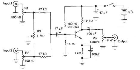
This audio mixer circuit diagram electronic project is designed using a few common electronic components. The audio mixer circuit project has two input channels. The input signal can be independently controlled using the R1 and R2 variable resistors. The...
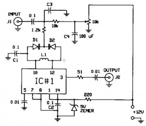
The FM modulator circuit, which utilizes frequency modulation, is constructed with a Motorola MC1648P oscillator. It employs two varactors, specifically Motorola MV-209, to achieve frequency modulation of the oscillator. A 5000 Ω potentiometer is incorporated to bias the varactors...
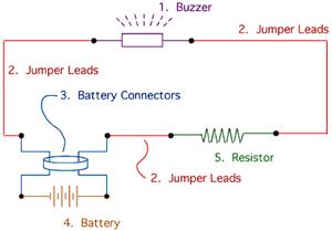
The drive circuit is a basic drive recently designed to accommodate a 27mm passive piezoelectric buzzer, aiming for a sound output exceeding 100dB while minimizing power consumption. Due to constraints related to product cost and structural size, the circuit...
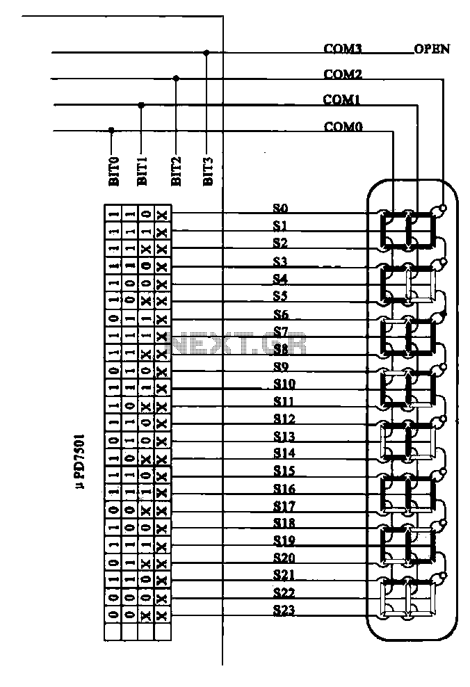
Examples of the structure of several liquid crystal display drive circuit CPU tubes. Liquid crystal display (LCD) drive circuits play a critical role in controlling the operation of LCD panels, which are widely used in various electronic devices. These circuits...
This circuit demonstrates how a low-drift preamplifier can enhance the measurement resolution of a thermocouple. The preamplifier is powered by the reference regulator, and bridge feedback is employed to bias the preamplifier input within its common mode range. Cold...
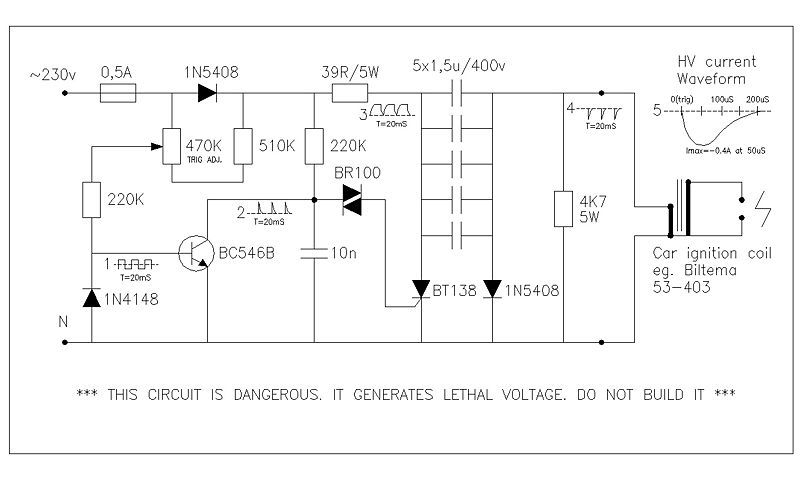
This circuit generates high voltage pulses from a 230 VAC line voltage. The drive end's swing comparator circuit was developed by the creator of this page. The working end is derived from a stroboscope trigger supply circuit. All circuits...